DS1307 Problems Again

LED Maestro

Senior Member
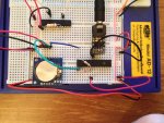
Hi, This is the third time I have had to ask for help with regard to this problem, with the previous 2 times, thankfully, being solved but in two different ways each time. Now the problem has resurfaced. My DS1307 RTC, connected correctly to a Pic28X2 via the SDA, SCL lines with appropriate pull-up resistors. See code below. When I debug, the hours, minutes and seconds just stay at 255 ($FF). I have tried re-programming multipul times with and without the pull-ups, changine the Pic and the RTC module, none of which solve the problem.

I feel stupid for asking yet again but this is vital to my final year project at college and my electronics teacher does not understand my project concept and is reluctant to help me solve my I2C comms troubles that I am currently experiancing, hence why I am now here. I dont need to go into details about what I need it for, I just need to be able to read the time from the RTC.

Any help is, as always, greatly appreciated.

Code:
#Picaxe28x2

symbol seconds = b0
symbol mins = b1
symbol hour = b2
symbol control = b3


; set PICAXE as master and DS1307 slave address

hi2csetup i2cmaster, %11010000, i2cslow, i2cbyte

; write time and date e.g. to 17:06:00 

start_clock:
let seconds = $00 ; 00 Note all BCD format
let mins = $06 ; 06 Note all BCD format
let hour = $17 ; 17 Note all BCD format
let control = %00010000 ; Enable output at 1Hz
hi2cout 0,(seconds,mins,hour, control)

main:
hi2cin 0,(b0,b1,b2,b3)
debug b1
pause 200
goto main
 

neiltechspec

Senior Member
I think you need to setup the DS1307 by sending everything to it - including the day of week & date.

hi2cout 0,(seconds,mins,hour,day,date,month,year,control).

Then when you read it back.

hi2cin 0,(seconds,mins,hour,day,date,month,year)

You need to send / receive all 8 variables, even if you aren't using the DOW & Date.

i.e.
Code:
set_clock:				;write time and date e.g. 08:52:00 on Sat 01/03/14
					;Monday is day 1, Sunday is day 7
	let seconds = $00		;00 secs
	let mins    = $52		;52 mins
	let hour    = $08		;08 hours
	let day     = $06		;06 day of week
	let date    = $01		;01 day
	let month   = $03		;03 month
	let year    = $14		;14 year
 	let control = %00010000 ;Enable output at 1Hz

	hi2cout 0,(seconds,mins,hour,day,date,month,year,control)
Neil.
 

neiltechspec

Senior Member
What voltage are you running it off & does it have battery backup.
If you have battery backup then supply voltage needs to be higher than batt volts for the chip to function.

Datasheet will tell you voltage requirements.
 

eclectic

Moderator
yep its got battery backup, 3.6V Litium Ion button cell, with a 4.5V main power supply.

Backup Supply Input for Any Standard 3V Lithium Cell or Other Energy Source.
Battery voltage must be held between the minimum and maximum limits for proper operation.
Diodes in series between the battery and the VBAT pin may prevent proper operation.
If a backup supply is not required, VBAT must be grounded.
The nominal power-fail trip point (VPF) voltage at which access to the RTC and user RAM
is denied is set by the internal circuitry as 1.25 x VBAT nominal.


From page 6, section 3 of

http://www.picaxe.com/docs/mic055.pdf


e
 

LED Maestro

Senior Member
Thanks for your reply. Ive had this module working for quite a few months. It's just a sudden lack of working when I tried to debug it to make sure it was still keeping time before implamenting it into my project. I have tried grounding the battery backup and even removing it completely but to no avail.
Thanks for the suggestion e
 

LED Maestro

Senior Member
Additionally, seeing as this was working not too long ago, and I havent changed the connections at all, apart from replacing the wires in case of internal breaks, is it possible that the RTC has stop counting? If that were the case though, wouldn't it return all zeros? is there a way to completly reset and restart the chip and oscillator?
 

neiltechspec

Senior Member
Disconnect it from supply & remove backup battery. That'll reset it.

Try it without the backup battery, as your supply voltage of 4.5v is borderline with a 3.6 backup battery (1.25 & VBAT = 4.5v).

Neil
 

LED Maestro

Senior Member
tried removing batt backup and module from main power. now currently back on the breadboard, reprogrammed with the current time without battery backup and still the same 255 for all variables. i understand that the CH needs to be cleared on start up but I am not learned anough with I2C protocol and comms to know if that is done within the code that I have.
 

hippy

Technical Support
Staff member
Reading all $FF suggests the RTC is not responding or the bus is not connected correctly. Even if the module isn't configured correctly, isn't counting time, the results should not all be $FF.

What tools do you have to help diagnose the problem; meter, scope, logic analyser, any other DS1307, any I2C EEPROM or I2C connected chips ?
 

neiltechspec

Senior Member
Always possible the chip has died.

Try another DS1307 or another PICAXE (almost any of them will do).

Are you sure you have sda & scl the right way round ?, I made a silly mistake like that once - had me confused for an hour or so.
 

LED Maestro

Senior Member
Thanks e, I honestly had no idea that was there. I did that, it said it was succesful adn it cleared the Pic memory, now I just run an hi2cin with all the variables, rembering to set the slave addresses etc but no time coding (i disconnected the rtc SDA and SCL lines just to be on the safe side) But I still get 255 as my variable values. Interestingly enough, Those values are present without the SDA and SCL lines being connected to the Pic. Why would this be? I can only assume because of the pull-up resistors but I tried removing them but with the same effect, static variables.
Any furthur help is appreciated at this point
 

LED Maestro

Senior Member
Please refer to post 1, I have already replaced the ds1307 and the pic but with no success. and yes i have tried the other way round and checked the datasheets to be user :)
thanks
 
Last edited:

LED Maestro

Senior Member
Thats what I thought hippy, it was odd to have all $FF. I have a multimeter yes but other than that, not an awful lot. I have already tested with another ds1307 but get the same results. Moved the components on the breadboard, different wires etc. The only other chips I have are SPI unfortunatly.
 

hippy

Technical Support
Staff member
With two PICAXE chips and two DS1307 modules showing the same issue it suggests the problem is not with either but the circuit or wiring between them, unless both PICAXE and/or both DS1307 have been damaged or are misbehaving.

When I run the code below on my 28X2 (ver B.4) with no I2C devices connected I get 255/$FF in both b0 and b1 with SDA and SCL pull-ups connected, and 209/$D1 in b0 and 255/$FF in b1 with the SDA pull-up removed. Might be worth giving that a try and seeing what you get ...

Code:
#Picaxe 28X2
HI2cSetup i2cmaster, %11010000, i2cslow, i2cbyte
Do
  HI2cIn 0,(b0,b1)
  Debug
Loop
 

LED Maestro

Senior Member
yeah i get the same results. And both the replacement picaxe and the ds1307 are new. I even tried with a couple of 28x1's but it doesnt work on them either. is it possible that the CH bit has not been cleared somehow, as that would stop it counting? Thats the only thing I can think of now.
Thanks
 

LED Maestro

Senior Member
I've just transfered the circuit onto another breadboard but, again, no luck. below is a picture of my circuit. Please ignore the upper left hand corner of the picture, thats not connected to anything. thanks
 
Last edited:

jims

Senior Member
Looking at the photo I can't tell if the "SDA" pin on the DS1307 module is connected or not. Jims.
 

Hemi345

Senior Member
If this is the same datasheet for your module, it looks like it already has 3K3 pullup resistors fitted for the I2C lines.

Also there was a discussion in these forums about D1, R4,R5,and R6 for the backup battery, but I don't recall what the recommendation/outcome was. I'll see if I can find it.

EDIT: here's the post I was thinking of.
 
Last edited:

neiltechspec

Senior Member
I have a couple of those modules (they look the same).

The 3k3 pullups are included on the clock module.

I removed D1, R4, R7, replaced R6 with a short & fitted a non rechargeable CR2032.

Threw away the supplied Chinese Li-Ion cell.

With a 3.2v VBAT backup battery, the RTC fails to function with VCC of 4v or less (1.25 X VBAT) - just tried it.

DS1307 is supposed to run off 5v anyway (4.5 is the minimum).
 
Last edited:

hippy

Technical Support
Staff member
The 28X2 has two 0V connection pins; both of which should be connected to 0V.
 

StigOfTheDump

Senior Member
Is the 4.5v supply measured at the batteries / PSU or at the chip? If I am reading your photo correctly there is a diode in the supply line or is it by-passed with the breadboard?
 

MartinM57

Moderator
If I am reading your photo correctly there is a diode in the supply line or is it by-passed with the breadboard?
Yes - that's interesting...

..is it a diode?
..what's it there for?
..why is it in the -ve supply line?
..do the -ve and +ve supply line "sections" on the breadboard really need connecting with wires, or are they connected to each other anyway - if the latter, the diode has no purpose/effect at all

Personally, I tried these Chinese DS1307 modules and had so many problems with them (poor timekeeping/weird schematic/contain an odd 3.6v rechargeable 2032 cell etc, and I have my suspicions whether the DS1307 is genuine or not) they are now unused at the back of the drawer.

Real, genuine, MAXIM DS1307 chips from reputable sources (Rapid, Farnell, RS etc), whilst more expensive, just seem to work fine first time and keep going.

(however IWP's point about the potential missing resistor on the PICAXE pin 1 is definitely the one to sort out first)
 

LED Maestro

Senior Member
Hi All, Thanks for your replies.

Jims, yes the SDA line is connected.

Hemi, I will take a look at the thread and give that a go. As I've previously said though, this module was working for a good few months before yesterday.

Neil, I have tried running without Batt-backup but did not work. I will try the modifications you suggest but again, it was previously working without any problems.

Hippy, yes I forgot to add the other ground connection, but this circuit, which I also used to run a binary clock off of, was working without it.

IWP, I was unaware there needed to be a pullup on pin 1, my apologies

Stig and Martin, I have a tendancy to confuse my positive and negative leads from my PSU, hence the diode to prevent reverse current and therefore possibly damaging the RTC and Pic. and yes the sections of the power rails do need to be connected via wires. Ive been looking into some of the RTC breakout boards from Rapid and RS such as the DS3234 which would be better suited to my project as it uses SPI, along with my other chips I'm using.

Thank you all for your help so far

EDIT: I will re-itterate again, this DS1307 module was working first time for a good few months and kept time perfectly. It is only now that, for some reason, it has stopped. I had this problem with another module, from a different source, but I was able to fix that one as the connection between the SDA jumper and the chip was secure. That does not appear to be the case with this module as I have checked the connections with my multimeter.
 
Last edited:

LED Maestro

Senior Member
Update:
After writing the above post, I went to reprogram the Pic and RTC. I had not realised I had left my breadboard powered overnight. I connected the pull-up to pin 1 and the second ground to the Pic and re-removed the battery from the RTC. I have just set the time and debugging and somehow it's working. I find it strange that I needed neither the pull-up of second ground when I first used this module. What I find more confusing is the fact that this is the 3rd time I have had this trouble with 2 different modules, all requiring 3 differnet fixes.
Still, I am always grateful for the help and support I recieve here
Thanks
Best wishes
 
Last edited:

BeanieBots

Moderator
...I forgot to add the other ground connection, but this circuit, which I also used to run a binary clock off of, was working without it....
Circuits will often work with a missing ground and even with a missing power connection.
This is due to a phenomena known as parasitic power.
That is when the circuit is powered (or grounded) via other I/O lines.
Results can be erratic because behaviour will depend on the state of the I/O lines.
Of greater concern is that I/O lines can be over stressed and hence damage one or more chips involved.
Please check your power connections to ALL devices carefully.
 

hippy

Technical Support
Staff member
I find it strange that I needed neither the pull-up of second ground when I first used this module.
Jupiter probably hadn't aligned with Mars :)

When a circuit isn't wired as it should be it can behave in weird and wonderful ways, often working when it perhaps shouldn't and then mysteriously stopping for seemingly no explicable reason.

Breadboard circuits which aren't quite right can be a particular nuisance with their long tracks under the cover. These may pull some signals high, pull some low, and randomly change the state of pins. Turn it one way it works, another way it doesn't, it may be okay when you are close to it and it can stop working as you walk away. Or vice versa. Or only on a Tuesday.
 

LED Maestro

Senior Member
Haha, very good point. Ive had quite a few problems with erratic inputs with and/nand & not gates on my breadboards.

Beanie, thats a very good point, I had removed my binary display before checking the RTC through debug so maybe that was part of the problem. I now know for future reference to apply all ground pins to ground. thanks.

Hippy, strangely I think it was actually a Tuesday when I first programmed my clock haha. And I have often found circuits on breadboard misbehaving but working perfectly when on PCB or strip-board, amplifiers, for example, are notorious for this in my experience.

My everlasting thanks to you all again for your help.
 

Hemi345

Senior Member
Circuits will often work with a missing ground and even with a missing power connection.
This is due to a phenomena known as parasitic power.
That is when the circuit is powered (or grounded) via other I/O lines.
I once wired a DS1337 on the breadboard backwards so that + was going to ground pin and negative to the + pin. The thing actually worked but then I started noticing weird things like the sun setting in the East and coming up in the West and my beard getting shorter...

Seriously though, the clock worked but was gaining about 5 seconds per minute in that configuration. I was very surprised it tolerated that.
 

LED Maestro

Senior Member
Haha well said Hemi. Yeah I've just checked my clock again and it's still keeping time so I'm very happy. I just need to work on the code for the display now which is daunting to say the least.
It does seem odd that yours managed to work with reverse voltage. I've often wondered why most modern ICs don't come fitted with an internal diode or something similar to prevent this type of thing happening. Still, I'm young and don't claim to know enough to be complaining about ICs. I'm just glad they work correctly when wired correctly!
 

hippy

Technical Support
Staff member
It does seem odd that yours managed to work with reverse voltage. I've often wondered why most modern ICs don't come fitted with an internal diode or something similar to prevent this type of thing happening.
There's most likely never any internal diode because it's not the chip's job to save you from your own accidents and mistakes. Adding one isn't useful nor necessary for the overwhelming number of chips used and can have other disruptive consequences if added.

Most power reversals will destroy a chip but often a chip fitted the wrong way round won't actually have it's power reversed but power fed in on I/O lines rather than the power pins. Internal clamping diodes can then still keep the chip powered and working to some extent. Whether it survives or is damaged is anyone's guess as it depends on what the actual incorrect circuit configuration is.
 

srnet

Senior Member
I've often wondered why most modern ICs don't come fitted with an internal diode or something similar to prevent this type of thing happening
Its not as simple as adding a diode, as the diode would cut the supply voltage to the IC, and a lot of modern ICs do run on very low voltages anyway, so putting a diode in line with the supply rail is not a good idea.

Some devices, such as some regulators, do indeed add additional circuitry to prevent damage in the event of reversal so this is often enough to protect the rest of the components.
 

Goeytex

Senior Member
Circuits will often work with a missing ground and even with a missing power connection.
This is due to a phenomena known as parasitic power.
This phenomena can be easily demonstrated by removing +V from the Picaxe and initiating a download. Many times the download will complete without error. The power is is being supplied from the USB or serial adapter through the serin pin, then internally to the Picxaxe V+ rail. The bypass capacitor will charge and keep the phantom power pretty smooth at the V+ pin allowing the download to complete.
 

LED Maestro

Senior Member
Srnet and Hippy, yeah as I thought, there was a very good reason for not having such a device in place. I realise there is a slight power drop using a diode but it seems to work fine for me. Just typing my thoughts without really thinking when I suggested it haha.

Goey, yeah I noticed that when I first started using picaxe. I used to do exactly that, download without the chip being directly powered. I was young and stupid at the time...not much has changed since really.

I do have another question but I think it would be better suited in another thread

Thanks again
 
Top