Driving Multiple Relays From a Single PICAXE Output

reywas

Member
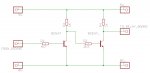
I have a positive-triggered, 16ch relay board that draws 3.8mA (measured) at each control input when the input is ON (High). The driver on the relay board is a darlington pair IC. I need to turn on 7 relays at once using a single PICAXE output pin. Obiously 7 x 3.8mA exceeds the 20mA max per pin current and, as you might imagine, it doesn't work correctly. I'm trying to figure out how to make this work with the limited components I have on hand. I have some 2N7000 N-channel FET's and I tried using a low-side switch circuit but it wouldn't source enough current through the pull-up resistor on the FET's drain. I know I could use a relay but I don't have one on hand and I'm out of room on the prototype circuit board.

Anyone know of a circuit using N-channel FET's that will work? I am open to ideas.
 

inglewoodpete

Senior Member
We really need more information to help you much. It is clear that the pull-up resistor you are using has a resistance too high to source the 7 x 4mA = 28mA required to turn seven darlingtons on.

You can calculate the resistor required by determining the voltage on the bases when each transistor is turned on (my guess is about 1.5v). The voltage across the resistor would then be calculated VResistor = Vsupply - Vbases. Ohm's law can then be used to calculate the resistance required: R = VResistor/Ibases (Ie R=V/0.03)
 

erco

Senior Member
Something's hinky here. You should be able to use a 2N7000 FET, a 2N2222A, or almost anything in between. Do you have any extra PICAXE output pins, perhaps the oft-overlooked serial output pin (which chip are you using?). That way you could simply switch both pins simultaneously in code, running 3 relays on one pin and 4 on the other, all in spec. The only downside is that your relays may flicker while programming. Another possibility is to reduce overall current draw with either a series diode or resistor from PICAXE output to the control inputs. How low can you go?
 

JimPerry

Senior Member
If you need to drive 7 and have 16 available - why not use 1 to control 7 and you still have 8 spare? :confused:
 

tmfkam

Senior Member
BC547_Relay.jpg

Something like this perhaps? Simple and reliable. You could do something similar with a single PNP, but I have loads of BC547 transistors and they aren't expensive if you buy them in 1000s (hence me having loads of them).

You could use only the first BC547 if you don't mind altering your code to switch the PicAxe pin Low to turn ON the relays, and High to turn OFF the relays.
 

AllyCat

Senior Member
Hi,

I don't see how you'd get the required 27 mA through a 1k resistor from 5 volts, especially as the Darlington inputs will need to be at least 1.5 volts above ground. :confused:

However, I'm surprised that each input needs 3.8 mA, the ULN2003A (7 x Darlingtons package) has about 7k across each input Vbe, so requires perhaps 100 uA.

But if you really do need 27 mA (and don't have a PNP), then what's wrong with an NPN emitter follower (collector to 5v, base to PICaxe output, emitter to the seven inputs)? But probably not possible using a 2N7000 as a source follower, because the gate threshold is too high.

Cheers, Alan.
 

reywas

Member
First to answer a couple of questions that were posed. The only output pin I have available on the PICAXE-14M2 is serial out and I'd prefer not to use it. There are no spare relays on the relay board.

I'm no longer convinced that the jittery relay problem is being caused by exceeding the PICAXE output pin max current. I did a bread board test using a PICAXE with one output pin (c.0) set HIGH driving the enable lines of the relay board. I started with 1 relay and worked my way up to 14, noting the V at the output pin and the I being sourced by it. Interestingly I found, that as I added relays one at a time, the voltage at c.0 dropped by about 0.25V to start with and by 0.1V at relay 14. Of course this meant that the current per relay was dropping each time I added one. One relay drew (drawed?, pulled?, required?) 3.53 mA at 4.66 VpinC.0 while 14 relays drew 1.41 mA each at 2.74 VpinC.0, a total of 19.81 mA. Seven relays drew 15.31 mA at 3.5 VpinC.0, which is the voltage I originally saw on my prototype board that led me to think the output pin was overloaded.

AlleyCat, I'm surprised at the 3.8mA number as well, given that the data sheet for the ULN2803 states a typical Iin of 0.35 mA at 5 V. There has to be something else on the relay board that is sinking current but I haven't traced it out yet.

I did get the low-side switch to work but I had to reduce the pull-up to about 290R.

I need to investigate the problem further to make sure I'm not barking up the wrong tree.

Is it ok to connect a PICAXE output directly to another PICAXE input? How much current would be drawn, typically?

Edit: Forgot to say that even with 14 relays enabled there was no jitter.
 
Last edited:

westaust55

Moderator
Folks do tend to forget that PICAXE (and other micocontrollers) outputs are not always at Vcc when driving a load.
When doing a calculation I tend to allow a volt drop of 0.3 volts which is greater than reality in most cases.

However the volt drop does increase with increasing load current on the output.


Yes, a PICAXE output can be connected to an input.
I recommend using a 220 Ohm resistor between the two in case a program accidentally dents both as outputs and 1 is high while other is low resulting is an effective short and maybe releasing the magic smokes.
An input only draws a few micro amperes.
 

AllyCat

Senior Member
Hi,

Is it ok to connect a PICAXE output directly to another PICAXE input? How much current would be drawn, typically?
Yes, it is permissible to connect PICaxe output to input pins and since the chip is CMOS the input current is basically zero.

However, it is generally recommended to connect a resistor between the pins (perhaps 1k) just in case the input gets "accidentally" configured as an output (and driven with an opposite polarity to the pin driving it). Also remember that until the output pin is configured as such (by the program) then the "signal" may be "floating" either high or low.

As for the Darlington drivers: You only need as much voltage on the inputs as is needed to operate the relays (reliably). That is probably around 2 volts and since the input impedance is basically non-linear (two forward diodes) the required current might not be particularly high. But do note that the PICaxe output "switches" are NOT "guaranteed" to pull up 20 mA, even with quite a large voltage drop. The P-channel (pull-up) FETs are significantly "weaker" than the N-channel (pull-down) FETs and the "20mA" is basically a "maximum rating" not an assurance that every chip can or will deliver it. Typical I/V curves are shown in section 31 of the "base PIC" data sheets for the M2 chips.

Cheers, Alan.
 

westaust55

Moderator
I'm surprised at the 3.8mA number as well, given that the data sheet for the ULN2803 states a typical Iin of 0.35 mA at 5 V. There has to be something else on the relay board that is sinking current but I haven't traced it out yet.
The TI datasheet: http://www.ti.com/lit/ds/symlink/uln2803a.pdf
at section 7.5 for IIon indicates with a 3.8 V input that the current is typically 0.93 mA and max of 1.35 mA.
three times higher than the 0.35 mA value you quoted but still three times lower than the 3.8 mA you measure.

Can you provide a link to the relay boards you are using. Do they, for example, have an LED as an indicator ?

Looking further at a Toshiba datasheet: https://www.adafruit.com/datasheets/ULN2803A.pdf
For Vin = 5 V, Iin = 0.35 mA to max of 0.5 mA
For Vin = 3.8V, Iin = 0.93 mA to max 1.35 mA
 

reywas

Member
Yes, each relay has an LED.

If you go to ebay and search for "16 channel relay module" you will get hundreds of listings for the same blue board with blue relays. I bought the positive triggered 12V version. None of the listings that I looked at had anything but basic technical info on the board. I took a look at the board and found that the inputs go to an optocoupler before going to the darlington-driver IC. The number on the optocoupler is B1422.
 

westaust55

Moderator
The LED in the opto-coupler is likely drawing a few mA to turn on the output transistor.
If each relay also has an LED to indicate when energsied is that across the opto-coupler input or connected elsewhere in the circuit?

Some searching found this Ebay site with schematics (with typos such as ULN2083 instead of ULN2803):
http://www.ebay.co.uk/itm/New-16-Channel-12V-Relay-Module-Arduino-PIC-ARM-DSP-AVR-/280825466634?pt=LH_DefaultDomain_3&hash=item4162808f0a
That shows the indicating LED on the output of the ULN2803.

So the LED in the opto-coupler is the reason for the 3.8 mA per relay channel as seen by the PICAXE.

There are 1 kOhm input resistors on the board by the schematic to control the current from PICAXE output to Opto Input.

I do not know what the opto-coupler input LED Vf is but for example if it were 1.8 V then with a 1 kOhm series resistor the control current per channel (from PICAXE) would be 3.2 mA.
T=If the the opto-coupler input LED Vf is 2.1 V then the current would drop to ~2.9 mA.
 
Last edited:

westaust55

Moderator
Further information from a similar board on Amazon:
2. The drive to each control input pin must "sink" 3mA when low (low = relay ON).
 

reywas

Member
That is the board I have but mine is the high triggered version. Not sure which component is different but the darlington driver IC's are socketed.
 

techElder

Well-known member
reywas, to my knowledge you haven't added a schematic to the thread showing how you have wired this board into your circuit.

According to the schematic that Westy dug up, the "difference" that you stated being "high triggered" or triggered with a low-going signal could simply be how you wired the opto's connections.

Optocoupler.jpg
 

reywas

Member
Ummm... I connected an output pin of the PICAXE to one of the 16 input pins on the relay board. I don't think a schematic is required to understand that.
 

westaust55

Moderator
That is the board I have but mine is the high triggered version. Not sure which component is different but the darlington driver IC's are socketed.
This is why it is far better that YOU give us a link to the data for the actual board you are using rather than send US off to try and find details for a similar board.

Are you directly connecting to PICAXE outputs or are you using a project board which itself has a Darlington driver chip resulting in a signal inversion.
This is why complete details can be far more helpful rather than feeding us with snippets of information.
 

tmfkam

Senior Member
Hi,

I don't see how you'd get the required 27 mA through a 1k resistor from 5 volts, especially as the Darlington inputs will need to be at least 1.5 volts above ground. :confused:
Sorry! The final resitor should have been 100R. That's copy and paste, coupled with poor attention to detail for you.
 
Top