Driving DC motor (fwd, rev, stop) Random Operation

oneshot

Member
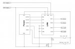
Im trying to build a circuit with a PICAXE to drive a 12VDC motor setup with forward, reverse and stop. I need the PICAXE source code set up for this operation:


1st configuration: The DC motor should only rotate forward and reverse 0 to 90 degrees. When it reaches 90 degrees a limit switch should then stop the motor and then go into reverse to go back to 0 degrees then the other limit switch stop the motor. Then at a random time between 3 to 10 seconds trigger the motor again to 90 degrees and repeat the cycle.


2nd configuration: Motor to go forward at 90 degrees then sense an overcurrent then reverse in the other direction at 0 degrees then sense overcurrent since it has reached its limit then stop. Repeat the cycle waiting 3 to 10 seconds randomly before it starts the new cycle again. The sense current circuit should be detected once the motor has reached its end points since the motor will be drawing more current when it has reached its end point limit stops.


I would like a circuit and program for both configuration.


Any help would be appreciated
 

premelec

Senior Member
Welcome to this forum- what you describe has been done many times with PICAXE units - please take the time to read up in the PICAXE manuals available for free - Manual 3 describes interfacing and for instance shows motor control using an L293D [p13].

How you have to do it in part depends on the current the motor requires - small low current motors take less power to drive.

In any case to drive 12 volt equipment from a PICAXE which runs on 5 volts requires level translation and external drivers.

Please give more information on your experience and equipment available and actual project description - would a servo motor do what you want? How fast does the motor need to move etc... all the timing and limit switch sensing etc can be done by a PICAXE. Manual 2 deals with instruction to do this. Do you have experience writing code to control things?
 

oneshot

Member
Hello premelec, project is for lifting a "shooting target" once it has been shot down. I have no experience programming or designing circuits. I do know how to build them and troubleshoot them but don't know anything about design or programming. I do have a complete PICAXE kit to get started on this project. The motor drivers and passive components if any I can purchase those locally.

I did download a free program called DipTrace which I can use to receive a circuit schematic diagram. Configuration #1 might be easier to build and would like to focus on that one first.
 

oneshot

Member
The DC motor im using has these specs:

COIL: 12V
Gear motor rated: 6.8 RPM @ 12VDC, .09A @ 12V No Load. 5mm (3/16”) dia. X 10mm (3/8”), flatted steel shaft, bronze bearings. Three M3-.5 threaded mounting holes in front. Solder terminals.
L: 2-11/16" (Body) Dia: 1-1/4" WT: .3
 

Jeremy Harris

Senior Member
The DC motor im using has these specs:

COIL: 12V
Gear motor rated: 6.8 RPM @ 12VDC, .09A @ 12V No Load. 5mm (3/16”) dia. X 10mm (3/8”), flatted steel shaft, bronze bearings. Three M3-.5 threaded mounting holes in front. Solder terminals.
L: 2-11/16" (Body) Dia: 1-1/4" WT: .3

You may want to consider using a servo instead of the motor. 0 to 90 degrees is within the normal range of cheap model servos and the Picaxe can very easily directly drive these with no external circuitry. My guess is that a paper target is very light in weight and should be within the range of most medium sized model servos. These servos come with an arm that moves through a a set range of angles and the Picaxe can directly command the actual angle using built in commands. This would remove the need for current or limit sensing and make the task pretty simple.
 

SAborn

Senior Member
It would seem you have most of the bits already, what is the picaxe kit you have??

The motor draws 90mA with no load, so a L293D driver chip would be suitable if the load is not excessive and with a high reduction gearbox like you have i doubt the load will effect the current very much.
With the L293D driver it allows for the 12v for the motor and the 5 volt for picaxe logic control, so thats all taken care of in the 1 chip.

6.8 rpm and 90 degrees movement would take 2.2 seconds to do, so plenty of time to monitor the limit switches.

One option might be just buy a L298 driver already mounted on a PCB off ebay for a few dollars and save the hassle of constructing that part, and the L298 has higher current rating should that be needed, also current limiting if that is actually used on the ebay boards (i dont know).

Then its basically plug and play, with a simple program to run the operation.

Edit..
Here is a link to a L298 driver, for $10 you get 2 driver boards, so a spare or perhaps a second target.

http://www.ebay.com.au/itm/180900717982?ssPageName=STRK:MEWAX:IT&_trksid=p3984.m1438.l2649
 
Last edited:

premelec

Senior Member
@oneshot - I hope I'm not confusing you by adding the following possibility: Gravity or a spring can be used to return a motor or motor pulley assembly to a fixed mechanical position. In short you drive the motor with a current limited source and it produces torque as long as current is applied... and free runs backward when motor current is ended - by spring or weight force pulling on the free running motor. I don't know if you have your mechanics worked out but it seems like this might work for you if the motor will free run with back force [not so easy through gear trains]. It would simplify driving forward and reverse - you just turn on or off and it raises a target or lets it fall... this is not so electric energy efficient but I don't get the impression this is a major problem.
 

oneshot

Member
Jeremy I considered using a RC servo but would need to be waterproof and have enough power to pull up the steel target. The target will be made out of steel, I won't use paper targets. This target model will be used for shooting .22 cal pellets and 22 LR rimfire ammo.

Saborn I have ordered the L298 driver board from ebay. Can you send me a schematic in how I should wire it up to a PICAXE and can you provide me with the source code program?


Premelec the geared motor is too hard and will not release with gravity or spring so a reverse circuitry will be needed.
 

premelec

Senior Member
OK - you can also simply use mechanical stops and sense the motor current which will go way up when it stalls against the mechanical stop [in either direction].
 

SAborn

Senior Member
Saborn I have ordered the L298 driver board from ebay. Can you send me a schematic in how I should wire it up to a PICAXE and can you provide me with the source code program?
I have not actually used the boards in the link, but have used the 298 driver, i had bookmarked the ebay drivers for a future project but not got to that yet.

When i get a little time to review what picaxe board you have (did you tell us??) and the ebay driver board then i will attemp a schematic, if someone else dont before hand.

What will you be using for limit switches? (micro switches perhaps)
 

boriz

Senior Member
I think limit switches (microswitches) are the way to go. Simple and robust.

How important is it that the targets 'present' quickly? How quickly? Will the Picaxe detect a hit? How?

Should be easy for a Picaxe. What's your programming/electronics experience?
 

JimPerry

Senior Member
I have not actually used the boards in the link, but have used the 298 driver, i had bookmarked the ebay drivers for a future project but not got to that yet.
Watch out for these boards - mine arrived with one of the terminal blocks mounted back-to-front - needed reworking to be usable :eek:
 

SAborn

Senior Member
Watch out for these boards - mine arrived with one of the terminal blocks mounted back-to-front - needed reworking to be usable
Hey? what do you mean???

From what i see its 2 terminals for 1 coil (or 1 motor) 2 terminals for the second coil (or second motor) a terminal block for V+ and ground, how can these be backwards?

The inputs are just header pins and can be wired to suit.

I dont doubt you knowledge Jim but dont see the problem here ( then im often blind in one eye and cant see out the other)

Some insight to what you found would be handy.
 

SAborn

Senior Member
Thanks Jim, that makes it much clearer (or fuzzy) one can only guess the sweat shop personnel had a few rice wines at lunch to make a mistake like that.
From your first comment i understood the circuit was backwards and was trying to understand just how that was.

I think i would have just claimed a new set of boards through paypal as it was not the same as the displayed item, paypal has a good system to cover these things and i have used it many times.

The old saying applies .... a squeaky wheel gets oiled, often a photo of the problem to the supplier will also result in a new shipment sent for no charge, with no return needed, China has picked their act up of late with the replacement of problem areas and seem to want a 100% feed back record and will replace most problems very quickly from my experience.
 

JimPerry

Senior Member
I sent them the photo and they said they would replace but never did :rolleyes:

Other suppliers have sent rapid replacements and/or refunds ;)
 

SAborn

Senior Member
I sent them the photo and they said they would replace but never did
You need to activate a claim with paypal also, i think you have 40 days from purchase, then if they dont send a new item paypal will refund your money and recover the cost from the seller.

Some sellers mess you around for 40 days so you miss your paypal chance.
Once you lodge a claim with paypal then you have time to escalate it to a full claim should you not be happy with the sellers response.

When you lodge a PP claim the seller is notified, so they do their best to solve the problem, i normally lodge a claim and send the seller a copy of the claim as well, then replacement parts get an express priority service on average, or i get my money back through PP.

I got messed around once long enough i could not make a PP claim, so i now know the rules and use them.

Works well for me, but only ever needed to use it a few times.
 

nick12ab

Senior Member
You need to activate a claim with paypal also, i think you have 40 days from purchase, then if they dont send a new item paypal will refund your money and recover the cost from the seller.
I thought the seller could require that you post the item back and you have to provide proof of delivery. The cost of doing that will make it not worth it, which is what the seller is hoping for.

ADDED:
For Significantly Not As Described claims, if eBay requires you to, you must post the item back to the seller, or to eBay, or to a third party at your expense and provide proof of delivery to eBay.
 

JimPerry

Senior Member
Exactly - Sending an £8.91 LCD screen back to China (with Tracking/proof) was more than £10 :(

After a while you get to know who to trust & repurchase from - latest adventure was with a less-than-£2 laser pointer - arrived in 5 days didn't appear to work. Replacement 5-days later - I'd put the batteries in the wrong way round - both work! Have told the supplier to let people know which way the batteries fit in future - and got a very nice thankyou email back saying keep both & they will tell customers in future :cool:
 

SAborn

Senior Member
Well all i can say is some of us have been around long enough to not always except what we read and challenge the seller.

It might be why the UK seems to get a lot rubbish dumped there from China, simply because you dont always take the rules to your advantage, i simply refuse to return post and offer it to be taken/sent to a local place of disposal, of PP choice.

If you can prove there is a genuine fault with the product then often there is little point returning it.

Once you lodge a claim then if it is not resolved, then i doubt you will leave good feed back, and as i quoted earlier China seems to want 100% feed back of late.

You can sit back and quote the rules if you want, but dont bitch to me you lost your money, when you can be proactive about it.
If PP gets enough claims against a seller they will remove that seller from PP access and or ebay as well.
 

oneshot

Member
Premelec that is what I plan to use is limit switches to stop the geared motor in both directions or instead of using limit switches setting up the circuitry in a way where it senses current and will stop automatically when it reaches its mechanical limit. (current limiting) similar to the circuitry used in automatic electric power windows used in aftermarket car alarms. If there is a circuit board already made for DC motors with current limiting I would like to know of a website where to buy it. Current limiting is nice to use because this way I will eliminate the 2 mechanical limit switches.

Saborn I have the 08M2 and the 20M2 PICAXE chips I was planning to use a mini breadboard for construction. I order all my PICAXE stuff from AZTEC. Can you tell me which is the best PICAXE board to use for this application? If I don't have it I will order it. I have mechanical and magnetic switches in hand that I can use but would be nice to use a current limiter circuitry to avoid using the 2 limit switches.


I would also like to make another model simply from an RC servo but I need to pick out a cheap servo that is waterproof and that can lift the metal target. The metal target will be about the size of an apple and thick enough to withstand the hit of a .22 cal pellet or .22 LR rimfire ammo.


I would like to enclose all of the mechanical and electronics below deck and target at the top. Also if someone is handy doing sketches of the mechanics please upload them to the thread so I get some ideas.

My main focus now is to build the electronics on this single target model. Id like to make a model using an RC servo motor with the PICAXE and another model using the DC geared motor using the PICAXE.


ONESHOT
 

premelec

Senior Member
Great - I have seen a bunch of intermittents or failures in various "microswitches" over the years... I guess hall switches would work fine and optical interrupters but the current sense should work well after a bit of tune up [initial current before motor gets going is high and needs to be ignored etc...].
 

SAborn

Senior Member
Ok here is a basic schematic sketch, of the L298 motor driver and Picaxe, i have not included the picaxe programming circuit as thats just a standard requirement.

The L298 board has 5v+ output on the board so this is used to supply the picaxe 5v+ (nice and easy there)
I show 2 limit switches, these can be any suitable switch, but i would not use the magnetic (reed) switches and most certain use a mechanical limit switch.

I do note you wish to use current limiting and will do another drawing using an Allegro current sensor, as they are cheap, premounted on a PCB, and very reliable, i just need some time to find a suitable supplier and product.


Motor Driver #1.JPG

Same drawing in PDF

View attachment Motor driver #1.pdf
 

oneshot

Member
Since the RC servo setup is simpler to do than the geared DC motor setup can someone tell me where to buy the board with the PICAXE to drive the RC servo directly and can someone provide me with the PICAXE source code / program to do this? I will need to use one switch to let the PICAXE know when the target is down that way it will not randomly be poping up when target is already in the upright position. Again I need the RC servo to trigger randomly between 3 to 10 seconds after target has been shot down.


The RC servo setup seems simpler to do, so I want to do this one first.


ONESHOT
 

oneshot

Member
Saborn thanks for making the schematic. Are the resistors 4.7K ohms or 4.7 ohms? I have not read a schematic in a while. Do they have a circuit board mounted with a PICAXE and this Motor driver IC in one single board that I can purchase outright instead of building it on a breadboard? On the schematic drawing what PICAXE chip is that the 08M2 or the 20M2 I didn't see the part number on it.


Saborn can you send me a PM


ONESHOT
 

SAborn

Senior Member
Gee i didnt think the motor driver circuit could be any simpler for a simple picaxe project, its all basic plug and play connections, other than the 2 resistors and 2 limit switches.

Whatever suits you best, are you sure you dont need someone to build it for you as well write the code as well.
 

SAborn

Senior Member
Can someone suggest a bare bones basic picaxe board that is either a 18m2 or a 20m2 board, as i dont know the codes for them or have ever used a Rev-Ed picaxe board.

All thats needed is the picxae and programming circuit with access to the I/O pins, if it has space for some pulldown (or pullup) resistors than that would be good, but not 100% required.
 

nick12ab

Senior Member
Can someone suggest a bare bones basic picaxe board that is either a 18m2 or a 20m2 board, as i dont know the codes for them or have ever used a Rev-Ed picaxe board.
Unfortunately many of the Rev-Ed boards, including the 18-pin and 20-pin boards, include darlington output drivers - you might not want those. And the PICAXE-08 project board has its strips perpendicular to the direction that they'd have to be in to enable you to just solder a 14 or 20 pin socket there (with the first and last 4 pins in the original 8 pins for the PICAXE).

This third party board appears to have a point-to-point wiring prototype area, so you could mount a 18 or 20 pin socket there instead of using the pads for the 8-pin PICAXE.

It would be best to search on your favourite supplier's website for a third party board that lacks gimmicks like the darlington driver, or just make your own on stripboard.

Finally don't forget about the PICAXE Experimenter Board.
 

oneshot

Member
OK will check that out. In the meantime if someone knows where to get a PICAXE board to drive an RC servo let me know, if there is not one available i will build the circuit to drive the RC servo I would just need a schematic and the PICAXE source code. The code needs to be RANDOM operation 3 to 10 seconds trigger, then repeat the cycle - like explained on earlier post.


ONESHOT
 

nick12ab

Senior Member
OK will check that out. In the meantime if someone knows where to get a PICAXE board to drive an RC servo let me know, if there is not one available i will build the circuit to drive the RC servo I would just need a schematic and the PICAXE source code. The code needs to be RANDOM operation 3 to 10 seconds trigger, then repeat the cycle - like explained on earlier post.
Rev-Ed sell this board for 8-pin PICAXEs which is marketed as a servo driver board. Most PICAXEs have built-in support for controlling servos (and not just the servo sold by Rev-Ed) and you can use servos on other project boards just by hooking up the servo wires appropriately, but if you need a large number of servos then look at the 21 Channel Servo Controller.
 

oneshot

Member
Nick12ab so the PICAXE-08 Servo Driver Board connects directly to the RC servo? I just see the 08M2 chip on that board. So the 08M2 drives the RC servo directly? Shouldn't it need more power, like a driver motor IC to drive that RC servo?


ONESHOT
 

nick12ab

Senior Member
Nick12ab so the PICAXE-08 Servo Driver Board connects directly to the RC servo? I just see the 08M2 chip on that board. So the 08M2 drives the RC servo directly? Shouldn't it need more power, like a driver motor IC to drive that RC servo
RC servos have built-in driver circuitry so all you need to do is connect the power supply to the servo and PICAXE, and the servo's signal wire to the PICAXE. The position the servo is at is determined by the pulse sent by the PICAXE, which can easily be done with the servo command.

For this reason no special external drivers are needed.
 

oneshot

Member
OK I got it now Nick12ab. Im using an external battery to power up the RC servo since I read they require at least 1 amp to power it up so the 6V source im using is powerful enough. Whats the highest voltage I can use to power up the PICAXE 08M2 ?

Im running my RC servo with the PICAXE 08M2


My next step is to find the source code to move the servo from 0 to 90 degrees then back to 0 degrees when triggered by an external micro-switch. So basically when the target is shot down a switch is pressed then activates the servo from 0 to 90 degrees then back to 0 degrees then stops until the cycle is repeated. I need the servo to complete the cycle in about 2 seconds so it does have to move somewhat slow so it won't damage the gears on the RC servo.

Another important function that the source code needs to have is that when the target is shot down and the micro-switch is triggered it should not activate the RC servo immediate but rather activated 3 to 10 seconds at a Random time, so never to trigger the servo at the same time but any time between 3 to 10 seconds.

If someone can write me the code for a PICAXE 08M2 for this type of function on the RC servo I would greatly appreciated.


Thanks

ONESHOT
 

nick12ab

Senior Member
PICAXE should only be powered with up to 5.5V. The absolute maximum is 6.5V but using above 5.5V may shorten the life of the PICAXE.

However the M2 parts do have internal regulators which usually means that they survive any overvoltage but that shouldn't be used as a reason to run it above 5.5V The pin driving transistors are internally connected before the regulator so that the output voltages are not limited to 3V so the output pins might get damaged.

Remember to connect the 0V connections on both power supplies to each other.

If someone can write me the code for a PICAXE 08M2 for this type of function on the RC servo I would greatly appreciated.
 

boriz

Senior Member
Your information is coming in drips and drabs and changing all the time.

If your question is general, like 'how should I do this?', then you will get general answers. Many, and sometimes conflicting.

If you're specific, like "I want to move a 12cm circular steel plate, 4mm thick, weighing 200g around this axis, this number of degrees within this many milliseconds....etc" then you will get a specific answer. However, this example is more an engineering question than a Picaxe question.

Don't ration your info. Be verbose, specific, and leave nothing out. (Make a note of that Watson)
 
Last edited:

oneshot

Member
Im looking for a PICAXE source code to function with these instructions. ------> Spin RC servo 0 to 90 degrees then back to 0 degrees and stop. When servo goes back 0 degrees it should trigger a switch will tell it to repeat the cycle once the switch is pressed. RC servo should turn on within a random time between 3 to 10 seconds. Can someone write me source with this function? It should take about 2 seconds to rotate the servo from 0 to 90 degrees.


ONESHOT
 

nick12ab

Senior Member
Im looking for a PICAXE source code to function with these instructions. ------> Spin RC servo 0 to 90 degrees then back to 0 degrees and stop. When servo goes back 0 degrees it should trigger a switch will tell it to repeat the cycle once the switch is pressed. RC servo should turn on within a random time between 3 to 10 seconds. Can someone write me source with this function? It should take about 2 seconds to rotate the servo from 0 to 90 degrees.


ONESHOT
Just added a bit to Rev-Ed's code example:
Code:
init:	servo 4,75	; initialise servo
main:	
	do
		random w0
	loop until w0 <= 10000 and w0 >= 3000
	pause w0
	servopos 4,75	; move servo to one end
	pause 2000	; wait 2 seconds
	servopos 4,150	; move servo to middle
	do : loop until switchinput = 1
	goto main	; loop back to start
 
Top