Andres Rodriguez
New Member
I am trying to drive a speaker with the output of a Picaxe. I would prefer to use 7.4V and would appreciate commens and/or suggestions regarding the attached schematic.
View attachment Speaker connection.pdf
View attachment Speaker connection.pdf
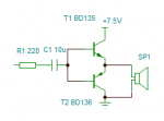
") ). The output of the PIC is a complementary pair of MOSFETs. One (P-channel) would charge the capacitor by taking the output pin high and the other (N-channel) would discharge the capacitor when the output pin is low.
). The output of the PIC is a complementary pair of MOSFETs. One (P-channel) would charge the capacitor by taking the output pin high and the other (N-channel) would discharge the capacitor when the output pin is low.