I got 2 each 08M and 18X chips from sparkfun.com and cannot get the program to download to them no matter what I do. I have tried all the things that it says in the "hardware not found" error window and still nothing. I see that the serout pin gives a high pulse on the oscilloscope when I attempt a download, so the chip is probably not burned out. I know that the hardware works because I have two Basic Stamp 2 microcontrollers and they work well. I also have a good understanding of the BASIC language so the program is probably not an issue. I would like to see if anyone has an idea of what is wrong.
Download Problem
- Thread starter LKK
- Start date
marcos.placona
Senior Member
Hi, it can be quite tricky in the beginning, but in no time you get a good grasp. You can take a pic of the way you're wiring it, and we can try to help ya. I've had the same problems in the beginning too.
Cheers
Cheers
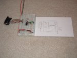
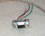
I made it on a bread board with the download circuit exactly like in the PICAXE manual with an LED on output 1. The adapter is a DB-9 socket with green wire to Rx, red to Tx, and black to GND.
A picture of the circuit and a diagram are in the attachment.
A picture of the circuit and a diagram are in the attachment.
Attachments
-
 466.4 KB Views: 34
Can we just be clear; after posting the photo you have connected 5V to pin1?
The 7805, do you have appropriate capacitors on in and out?
Can you stick you 'scope directly across PICAXE power pins to check smoothness of power?
(Measure directly on the i.c. so that will also confirm it's stuck in the breadboard properly. Might also be worth checking all pins to make sure breadboard/chip connections are good)
marcos.placona
Senior Member
I might be wrong here mate, but on your breadboard, the 10 and 22k don't seem to be connected together, or are they?
UPDATE: Nah, just looked again, and they are.....
UPDATE2: Why is the 10k resistor going to leg 8? Not sure if this can interfere, but try to connect it directly to 0v line
UPDATE: Nah, just looked again, and they are.....
UPDATE2: Why is the 10k resistor going to leg 8? Not sure if this can interfere, but try to connect it directly to 0v line
Last edited:
marcos.placona
Senior Member
That shouldn't make much of a difference. I've been using the same setup with no problems at all
hippy
Ex-Staff (retired)
Apart from that +V/Leg1, I cannot see anything else wrong with the circuit or your breadboard setup. That points to either the Programming Editor not configurd for the right port, cable plugged into wrong port, or 9-way plug mis-wired.
As you have a scope - disconnect the download cable, monitor leg 7 ( Serial Out ) while connecting Leg 2 ( Serial In ) to +V ( you can leave the 22K/10K in place ). You should see a pulse train on Serial Out. You may have to wind the timebase to around 5mS to see the pulses.
Another alternative is to disconnect the 9-way D to 22K lead, keep 0V and Serial Out connected, connect Leg 2 to +V as above while monitoring the COM port using the Programming Editor Terminal function at 4800 baud. You should see a burst of characters all the same.
Please don't take this the wrong way, but this is another reason why people new-to-PICAXE should buy the cheapest project-board with built-in download circuit first - sorry to go against Stan's breadboard-flow.
Are you sure you haven't got Rx/Tx reversed on 9-way? I can't check from photo.
Have you checked the electrical connections of chip into breadboard?
Are you sure you haven't got Rx/Tx reversed on 9-way? I can't check from photo.
Have you checked the electrical connections of chip into breadboard?
I think it is wired up right but would it be possible to take another photo from another angle maybe zoomed in a bit, and with the 5V wired in? Also are you using a PC or a laptop? Can you measure the volts on pin 3 of the D9 plug, both when the chip is 'resting' and also when downloading? Also try turning the power off, then turn it on just after clicking on the download button.
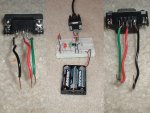
I have only one COM port through a USB to RS-232 adapter, my computer does not have a serial port. I know it works because I program my other microcontrollers with the same port. I think that the wires on the serial connector are correct because I used it with some other projects. I tried the 100nF caps, I still cannot download. A fresh 3 AA battery pack that I measured at 4.7V didn't help either. I made another picture with the board on battery power. The red LED is just a power indicator. I also provided a close-up view of the connector.
EDIT: I have a desktop PC, not a laptop.
EDIT: I have a desktop PC, not a laptop.
Attachments
-
 322.9 KB Views: 25
I am trying to make some measurements, I noticed that pin 3 on the DB-9 connector measures -0.16V, but when I disconnect pin 2 from the picaxe, pin 3 falls to -4.2V. when disconnected, pin 2 on the connector is -4.2V, and rises to -0.2V when connected. The picaxe serout pin measures 0V when disconnected. When I hook the oscilloscope to pin3 on the connector with everything hooked up to the picaxe, I see a 500kHz sawtooth alternating between -5 and -3V. when pressing the download button, the sawtooth alternates between 4 and 5V, and stays high until the error message is shown. Again, with everything hooked up, serout shows a sawtooth alternating between -0.6 and -0.3V. when attempting download, the sawtooth rises to about .3V, and after a second gives out a train of pulses just lasting for a split-second.
Last edited:
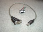
That D9 connector - is it male or female? I can't see from the photo. I gather you are using a USB to D9 connector - is that right? If so, is it one of these? http://www.rev-ed.co.uk/images/full/USB010.jpg If so, that implies the D9 you are using is female, and if so the pins might be transposed. Your pins look right for a male D9 but I'd expect a female. RS232 is very confusing - pin 3 is an output if the device is a computer but is an input if the device is a modem. You should have -9 to -12V on pin 3 and your measurements suggest that isn't the case. Can you pls take a photo looking from the other side so we can see the D9 plug? Also I'm concerned about the reading of -4.2V on pin2 of the D9(?)- that could zap a picaxe output and it should be reading 0V (open circuit technically) as it is an input.
Last edited:
I think I found a big problem but I do not know how to fix it. When I hook serin to +V then I reliably get a train of pulses on serout. But if I set the terminal program to 4800 baud, nothing happens when I pull serin high. I know it is not the connector because I still get the pulses on the oscilloscope if I plug the probe directly into the socket.
EDIT: The socket and adapter are shown in the attachment. The cable is male on one end and female on the other. The pins on the connector are correct, it worked with other projects and I checked it a few times.
EDIT: The socket and adapter are shown in the attachment. The cable is male on one end and female on the other. The pins on the connector are correct, it worked with other projects and I checked it a few times.
Attachments
-
 462.9 KB Views: 12
Last edited:
Not sure but those voltages are not right on the D9 plug. Is the one in the photo male or female? I'm trying to second-guess by looking for the 3 notches that are on male plugs but the jpg is too compressed. Also the terminology is getting confusing - when you say serin do you mean serin as in pin 2 on a D9 male plug or serin as in physical leg 2 of a picaxe chip?
Last edited:
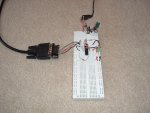
I tried to expirement with my PICAXE-18X, same results but 50% of the time the serout pin goes high for a split second instead of giving a pulse train.
And here is the program I am trying to download (for bout microcontrollers):
do
high 1
pause 500
low 1
pause 500
loop
Note that the LED is hooked up to out 1 of the 18X, not 0.
And here is the program I am trying to download (for bout microcontrollers):
do
high 1
pause 500
low 1
pause 500
loop
Note that the LED is hooked up to out 1 of the 18X, not 0.
Attachments
-
 470.9 KB Views: 8
See the photo - on my D9 the orange circled pins are pin 5 which is 0V. Can you confirm you have a tiny 5 next to that pin? Pin 5 is ground. I think the D9 needs rewiring?
Attachments
-
 44.4 KB Views: 13
Last edited:
hippy
Ex-Staff (retired)
Your socket is wired wrong
Your female socket to breadboard is wired wrong. You have 0V to pin 1 not to pin 5 and the rest are consequently wrong as well..
The diagram shown in your circuit is right for a connector when viewed from the soldering side but not from the inlet side.
Your female socket to breadboard is wired wrong. You have 0V to pin 1 not to pin 5 and the rest are consequently wrong as well..
The diagram shown in your circuit is right for a connector when viewed from the soldering side but not from the inlet side.
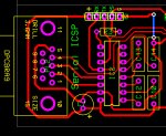
Here's a bit of an old CAD using a Tyco female D9 into a PCB.
By the way... it worked when I last used it.
(Ignore socket pin 4)
By the way... it worked when I last used it.
(Ignore socket pin 4)
Attachments
-
 269.2 KB Views: 15
marcos.placona
Senior Member
It's funny, but the most common of the download issues is the connector, and it seems to repeat with 90% of all the users.
marcos.placona
Senior Member
Hi Dippy, I think I didn't express myself properly here. I didn't mean to blame the connector, but to blame the connections. I just wanted to say that most of the problems are connection (to the connector) related.
Some time, when people use rev-ed's download cable (which is my case), they easily swap wires and get it all wrong.
As an example: The stereo connector has 6 pins, 4 close to the actual connector (two on each side) and 2 in the very top.
On my first connection, I remember that it was eclectic who told me to have the pairs joined together.
Honestly I'd never guess that at the time I started...
And this is why I'm saying that most of the download problems and related to the connector.")
Some time, when people use rev-ed's download cable (which is my case), they easily swap wires and get it all wrong.
As an example: The stereo connector has 6 pins, 4 close to the actual connector (two on each side) and 2 in the very top.
On my first connection, I remember that it was eclectic who told me to have the pairs joined together.
Honestly I'd never guess that at the time I started...
And this is why I'm saying that most of the download problems and related to the connector.
Last edited:
hippy
Ex-Staff (retired)
The best way to avoid connection problems is to use a pre-built board or take a physical known working reference to copy, and failing that to work to the reference specification provided.
Page 31 of PICAXE Manual 1 clearly shows how to wire up a 3.5mm socket, 3-way molex and a 9-way female D.
Wiring up 9-way D's is often a nightmare; is it DTE or DCE, male or female, cross-over or not, does "TX" mean TX from something else ( ie, RX to this ) or does it mean TX from this, is "furthest left pin" viewed from the front or back, so no surprise Rev-Ed provide a ready-built 9-way to molex and then moved to 9-way to 3.5mm, "guaranteed to work".
Maybe Rev-Ed need a specific document which details how to wire up the various connectors plus the checklist for getting a DIY circuit up and running. The information is all there but, time and time again, we do encounter people who still get it wrong.