Hello all, please critique this idea for reusing output pins.
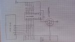
I want to use the same pins to drive a 16x2 lcd and drive 5 miniature solenoids. I propose to use 7 pins in total. The solenoids only need to be pulsed one at a time, for a few milliseconds, drawing a couple of hundred milliamps.
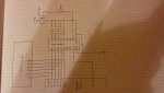
To send data to the lcd I will put data onto out1 to out5 and pulse out6.
To activate a solenoid, I would set out7 high and then pulse one of out1 to out5.
I have drawn a heavy duty logic level power fet, but would a bc337 do just as well? Or a bc327 on the high side?
Thanks,
Paul
I want to use the same pins to drive a 16x2 lcd and drive 5 miniature solenoids. I propose to use 7 pins in total. The solenoids only need to be pulsed one at a time, for a few milliseconds, drawing a couple of hundred milliamps.
To send data to the lcd I will put data onto out1 to out5 and pulse out6.
To activate a solenoid, I would set out7 high and then pulse one of out1 to out5.
I have drawn a heavy duty logic level power fet, but would a bc337 do just as well? Or a bc327 on the high side?
Thanks,
Paul