Do you have an oscilloscope and an R/C receiver?

nfk

Senior Member
Hi,

I have not had any luck trying to solve a problem with accurately measuring pulse width from R/C receivers (http://www.picaxeforum.co.uk/showthread.php?t=8410) so could I ask for YOUR help! If you have an oscilloscope and an r/c receiver (or other r/c-type signal source) could you please try the following:

1. Wire up a Picaxe chip (I'm using the 18X and 28X1 chips) so that the signal output from a channel on the r/c receiver goes into input 0 on the chip (mine have been mounted on the standard Picaxe Experimenter Board which is powered by the same 4.8 volt supply as the receiver). I you use an r/c receiver you may need to switch on the transmitter so that the receiver will generate a signal. I used a little servo testing gadget instead.

2. Program the Picaxe chip with this simple code:

Code:
main:		pulsin 0,1,w1
		pulsout 0,w1
		goto main
3. Use the scope to examine the output from output 0.

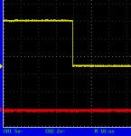
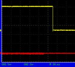
The signal should be rock solid but every time I try it the signal is read inconsistently causing the output to be correspondingly slightly unstable. If you get the same result you will see the signal on the scope vary slightly in length. This means that if I put a servo on the output it jitters slightly. It's odd because the rate of jitter varies. I have no idea why!

Obviously if you get the same problem as me the challenge is to try to fix it! You'll see from the other thread that I have tried all sorts of things to make it work, e.g. tying the outputs low with resistors etc. but nothing seems to work. I know I could smooth out the output with software but that is not an option as I have to make the servo as responsive as it is capable of being. It has to be a hardware solution.

PLEASE HELP!!!! :eek:

Many thanks,
Nigel

PS Here's my setup below...

 
Last edited:

hippy

Ex-Staff (retired)
How jittery is the output - Is it a matter of +/-10uS or somewhat larger ?

Because of the way the PICAXE ( and any polled pulse sampling scheme ) works there's always the likelihood of some jitter. It's not deterministic when polling starts and the processor isn't synchronised with the incoming signal. Exactly when it sees a pulse start or end can therefore vary for each sample.

Two things you can try (1) running at 8MHz which increases sampling rate and should decrease the chance of missing a start or end of pulse, and (2) trying to force the PulsIn to be more deterministic ...

Code:
main:   pulsin 0,1,w1
        pulsin 0,1,w1
        pulsout 0,w1
        goto main
You'll only get half as many pulses out as you put in so it may not work with a servo but you should still be able to tell whether that reduces jitter on the scope.

Beyond reducing the jitter caused by real-world hardware interactions, all you can then do is go for software compensation. Untested, but this may work ...

Code:
Symbol RX_PIN            = 0
Symbol TX_PIN            = 0

Symbol counter           = b0
Symbol direction         = b1
Symbol this              = w1
Symbol current           = w2
Symbol temp              = w3

Symbol GOING_DOWN        = 0
Symbol GOING_UP          = 1

Symbol COUNT_NEEDED      = 10

Symbol ZERO_COUNT        = $80
Symbol UP_COUNT_NEEDED   = ZERO_COUNT + COUNT_NEEDED
Symbol DOWN_COUNT_NEEDED = ZERO_COUNT - COUNT_NEEDED

PulsIn RX_PIN, 1, this
PulsIn RX_PIN, 1, current
If this <= current Then
  direction = GOING_UP
End If
counter = ZERO_COUNT

Do
  PulsIn RX_PIN, 1, this
  If direction = GOING_UP Then
    If this >= current Then
      current = this
      counter = ZERO_COUNT
    Else
      temp = current - 1
      If this < temp Or counter <= DOWN_COUNT_NEEDED Then
        current = this
        direction = GOING_DOWN
        counter = ZERO_COUNT
      Else
        counter = counter - 1
      End If
    End If
  Else
    If this <= current Then
      current = this
      counter = ZERO_COUNT
    Else
      temp = current + 1
      If this > temp Or counter >= UP_COUNT_NEEDED Then
        current = this
        direction = GOING_UP
        counter = ZERO_COUNT
      Else
        counter = counter + 1
      End If
    End If
  End If
  PulsOut TX_PIN, current
Loop
Added : I know you don't want to use software smoothing to get maximum responsiveness, but it's worth trying to see what unresponsiveness it introduces if any. If the code is too slow it can (1) be run at 8MHz, (2) optimised to be faster.
 
Last edited:

moxhamj

New Member
That CRO tracing looks rock solid. If there were jitter on the output then the vertical line as it goes from high to low would be smeared out in the x direction. So it appears that pulsin is the problem. The code is so simple that the only explanation I can think of is that this is coming up against the limits of the picaxe. I gather you don't want jitter because it looks unprofessional in a product you might sell. So if you are up against the limits of picaxe accuracy I'd have to agree with Hippy about software smoothing. There are lots of filtering algorithms but the one I'd look at is to read a value and then take the next value and if the absolute change is (say) less than 3 then output the original value, and if it changes more than 3 then presumably the input really has changed and move the servo to the new value. I'm not an expert on servos but I would have thought that backlash in the gears and play in the linkages may contribute more of an error than this. I know that isn't the answer you want and certainly try Hippy's idea of going up to 8Mhz. There is also the option of getting into the raw PIC machine code.

Re resetting, simple code would be
start: high 1
pause 100
low 1
main: etc

And then at least you can see a led flashing if it does reset. Have just noticed the other thread about fingers on components. That kind of suggests parasitic RF. Playing around with audio amps it is not uncommon to touch a component and hear a local AM radio station. I presume the power supply has the correct bypass components - sometimes they can break into megahertz oscillations. The CRO should help here - sweep through all the timebase settings while measuring the 5V rail etc. Ground hum loops are another possibility - you can hear these obviously in an audio amp but in a picaxe you would never know. Bring grounds to a common point rather than looping the ground from one component to the next.
 
Last edited:

goom

Senior Member
It is certainly possible to get jitter-free servo operation from a simple pulsin/pulsout at 4 MHz. I recently put together a mixer with 2 inputs and output to 4 servos.
One of the servos was an old and worn one, and it did jitter from time-to-time. Input was from a 2.4 GHz radio (Spektrum), so perhaps this system is more stable than other transmitter/receiver units.
I have encountered jitter with direct receiver to servo connection if the transmitter was particularly close to the receiver.
The circuit was built on a PCB with large areas of ground plane between circuit traces.
Hope there are some clues here as to the source of your jitter.

As to not reading the center position (150) correctly, I read the neutral position once at the start of the program. All subsequent readings are then interpreted as a difference from this initial null for the purposes of, for example, providing an output to a PWM speed controller. If you are outputting to a servo, I would assume that any error in pulse width would be equally applicable to pulsin and pulsout, so no adjustment necessary.
 

nfk

Senior Member
Whew! So much to reply to!

First of all, very many thanks Hippy for all that code - I tried it and, as expected it does indeed work nicely (yes, the jitter is around +/-10uS). However my problem is that, as Dr_Acula says, I am trying to produce a product for other people to program and it wouldn't look good if my customers had to use code to get around a problem like this. For the same reason using machine code isn't an option either. By the way I checked to see if this was caused by the chip doing a reset but it isn't.

Dr_Acula, the trace in the picture may look solid but the horizontal line jitters as you watch it (i.e. varies in length by a few mm). The frequency by which it jitters varies over a period of 10 or 20 seconds. Not sure what you mean regarding the power supply - as you can see from the photograph I am powering the unit with a battery so ground loop hums shouldn't be an issue.

Goom, you mention that you have managed to obtain jitter-free operation. I wonder if you were using high performance digital servos? Apart from seeing the jitter on the oscilloscope trace I am also testing this simple system with Futaba 9252 and 9254 digital servos. It is possible that with a standard analogue servo you wouldn't notice the jitter as it is relatively small, i.e. +/-1%. Although this doesn't sound very much it is certainly visible and, as mentioned previously, it has to be right if I'm to make a product out of it. What I need is a hardware solution.

I hope someone else will try this out and confirm my results.
 
Last edited:

eclectic

Moderator
Bad news? Good news?

Nigel. I don't know if this might help or not;

Caveats first.
1.The results are displayed on a Cheapo-Scope, (not Tectronix).
2.The tests were in an extremely noisy room. (2 computers, wireless, 'scope, etc.)
3.I don't have any R/C gear, so I used an 08M for the “transmitter”, using

#picaxe 08M
sendout:
servo 2,150
pause 10000
goto sendout

I used your “receiver” program on a 28X1

My results are totally in line with Hippy and Doc's observations.
The trace jittered by ~10 – 15 us.
(But please see notes 1 and 2 above)

A possible for your next trial is to use a battery powered 'scope, in the
middle of a large field, to reduce EMI?

e.
 

Attachments

nfk

Senior Member
Thanks eclectic,

Reassuring to hear you're getting the same results as me!

(Added: Just to be clear, the jitter is in the length of the pulse - I notice in eclectic's pictures there is vertical interference on the trace, i.e. the measured voltage - this would not cause jitter)

Just to show that I don't want to leave ANY stone unturned, I followed your suggestion (which I know you didn't necessarily mean me to take seriously) and took the circuit outside into a large field (despite the appalling weather we are having) and tried it there with a battery as a power source and a servo as a 'monitor'. Sure enough, the problem was still there (meaning that interference is unlikely to be the problem). As a control, I removed the circuit and plugged the servo directly into the signal source and it was as solid as a rock.

My next experiment (when the parts arrive) will be to try a 28X1 with a 16MHz oscillator to see if further increasing the clock speed has any beneficial effect.

Cheers,
Nigel
 
Last edited:

eclectic

Moderator
16MHz

Nigel.
I set my 28X1 receiver, using em 16.

I haven't posted pics, but the results look similar to my earlier posting,
except that the bounce/jitter is now about 2.5 us.

e.
 

nfk

Senior Member
Thanks for your help with this eclectic,

I've just tried a 16MHz resonator. The jitter is still there unfortunately although the amplitude appears to be smaller - I think I'm getting exactly the same result as you.

Hmmmmm...not sure what else to do. As far as high performance servos are concerned I think I'm probably going to have to live with this one or wait until the long-awaited X2's arrive with which I guess we'll be able to clock them up to 40MHz and reduce the problem still further.

(I tried the 16MHz setup with a fairly standard Futaba S9001 servo and it's fine - it's only high performance servos that see this problem. In fact, I guess you could say that this circuit is a good test to see if servos really are high performance!)

Nigel
 
Last edited:

leftyretro

New Member
Thanks for your help with this eclectic,

I've just tried a 16MHz resonator. The jitter is still there unfortunately although the amplitude appears to be smaller - I think I'm getting exactly the same result as you.

Hmmmmm...not sure what else to do. As far as high performance servos are concerned I think I'm probably going to have to live with this one or wait until the long-awaited X2's arrive with which I guess we'll be able to clock them up to 40MHz and reduce the problem still further.

(I tried the 16MHz setup with a fairly standard Futaba S9001 servo and it's fine - it's only high performance servos that see this problem. In fact, I guess you could say that this circuit is a good test to see if servos really are high performance!)

Nigel
Very interesting symptom you have uncovered. Do you know what the typical "digital servo's" internal A/D converter uses for resolution, 10,12 or other bits? I could be that the basic resolution steps that the Picaxe can output are much courser then the servo A/D converter and it will 'seek' around within the Picaxe's resolution?

Just a thought

Lefty
 

nfk

Senior Member
Hi Lefty,

I don't know anything about the internals of digital servos but there is some information about (Futaba) digital servos here...

http://www.futaba-rc.com/servos/digitalservos.pdf

I expect this is an important part of the article...

...a digital servo sends pulses to the motor at a significantly higher frequency. This means that, as opposed to the motor receiving 50 pulses/sec., it now receives 300. Although the length of the pulses is reduced in a direct ratio to the higher frequency because the power is being turned on/off to the motor more frequently, the motor has more incentive to turn. This also means that not only does the servomotor respond faster to the commands, but that increases or decreases in power for acceleration/deceleration are able to be transmitted to the servomotor far more frequently. This gives a digital servo an improved deadband, a faster response, quicker and smoother.
Cheers,
Nigel
 
Last edited:

moxhamj

New Member
Can you please clarify the test set up a bit more? It seems from the description that it is pulsout that is producing the jitter. Up till now I (and a few others I think) have been assuming the pulsout is steady and the problem is with pulsin. So if pulsout is varying (and maybe there is nothing wrong with pulsin) then this opens up some other avenues to test. Do you have a 555 you could set up to produce the pulses?
 

nfk

Senior Member
Dr_Acula,

No, you are quite correct - the problem is with PULSIN. It does not read the pulse value consistently. The test setup for 4/8 MHz is shown in the picture at the top of this thread. I can post a picture of the 16MHz setup if you like but it's very simple.

I guess I could use a 555 timer to generate the pulses but I have no reason to believe that there is anything wrong with either the servo tester that I am using or the receiver that I originally noticed the problem on. They drive digital servos perfectly and the signal is perfect on the 'scope. Additionally, 'eclectic' used an 08M to do this test and got the same results.

Even Hippy's more deterministic code...

Code:
main:   pulsin 0,1,w1
        pulsin 0,1,w1
        pulsout 0,w1
        goto main
...doesn't work (a shame - I though it was quite a good idea).

Anyway, I would need to find a hardware solution - I can't ask people to use code to get around this.

Cheers,
Nigel
 
Last edited:

nfk

Senior Member
Further to the above, I thought I'd just prove beyond reasonable doubt that it is indeed the PULSIN command that is causing the problem. I just tried this little bit of code which sends a fixed value to PULSOUT...

Code:
main:		pulsin 0,1,w1
main2:	        pulsin 0,1,w2
		pulsout 0,w1
		goto main2
...and sure enough the servo is steady as a rock.

I think that this shows that there isn't anything wrong with PULSOUT.

Cheers,
Nigel
 

Technical

Technical Support
Staff member
As both Hippy and ourselves have already tried to explain in this thread and the previous thread, the pulsin command in this situation may always vary by +/-1 each iteration. There is no way around this in PICAXE hardware. As previously quoted:

It can take the chip between 1 and 10us to actually detect the start of the pulse, depending on the position within its assembler code 'standby loop' when the pulse actually starts. This can cause a difference of +/- 1.

So to clarify you will never get exactly what you want to achieve in this situation from the PICAXE. The start of the pulse within the 'standby' loop code is an uncontrollable element, and can cause a difference of +/- in the pulsin command value.

By the time this value is transferred to the pulsout command it becomes a +/- 10us difference, as you have seen on the scope.

However this is easily compensated by software. It is also easy to publish a standard sub-proocedure to do the correction, third parties do not necessarily have to understand it to use it!

e.g. tell people to use
Code:
main:   pulsin 0,1,w1
        gosub compensate
        pulsout 0,w1
        goto main
and just have the 'compensate' routine as a pre-saved template!
 

moxhamj

New Member
NFK, I hope that doesn't mean you are giving up on the project? Technical's 'compensate' routine only needs to be a few lines of code.

There may still be other hybrid picaxe/analog solutions. Say you have a circuit that charges a capacitor using a constant current and that is driven by the pulse. Read the value with readadc10. This is just an idea and I haven't tested it, but the resolution may well end up being better than 8 bits. It would probably need a sample and hold circuit and a fast discharge circuit but these are not complex. Chip count might be 3-4 chips.

But code in a picaxe is simpler.
 
Last edited:

hippy

Ex-Staff (retired)
I can't ask people to use code to get around this.
I'm not sure why not. If you're not giving them source code they'll never know. If you are giving them source code then they'll most likely understand, or not care. The challenge is delivering a solution which works as well as is needed, not how it's implemented, unless there are other aspects to this project you've not disclosed ?

In your orginal posting you say you want to read the pulse in, modify it, then output it again. This smoothing would be little more than the processing you are already planning to do, a part of it as it were.

Perhaps if you provide the details of what it is you are actually trying to achieve on a larger scale rather than looking in detail at just this specific technical problem there may be other ways to get round it.
 

nfk

Senior Member
To be honest I think the 16MHz route is the best one. Although the jitter is still there it is reduced to a level which I hope will be acceptable.
 

jglenn

Senior Member
Technical: at first I thought his scope trigger was not set right, but it seems there is a resolution limitation of PULSE in. Is this like the nyquist criterion?

You have to sample a signal at 10 times its highest freq. for accurate reproduction? Or measurement?

I am getting close to using my picaxe for other that the flashing light test that's been running a month. Will be wary of pulse in.:cool:
 

Technical

Technical Support
Staff member
It's simply a limitation of the PIC at 4MHz - each raw assembler code instruction takes 1 or 2us to execute. Whilst waiting for the pulse the assembler code loop has to repeatedly read the input to see if it has changed. The loop has to also clear the watchdog timer and increment/test for the timeout etc.

So basically the polling loop is made up of a handful of assembler instructions which take 10us to cycle, or put in other words, the PICAXE just checks for a changed condition every 10us. Depending on when the pulse changes you might be reading at that very instant (no delay) or have to wait a full 10us (just missed). This basically can give a +/-10us error between subsequent readings.

However the resolution of pulsin is 10us steps, so this gives a +/-1 difference in the pulsin variable.

For most applications this doesn't really matter, but if you need to you can easily compensate for as already described in these threads.
 

hippy

Ex-Staff (retired)
It's also true to say that all polling mechanisms suffer from the same problem and it is not just peculiar to the PICAXE. If the PICAXE / micro is run faster then the jitter reduces in size and at some point the amount of jitter reduces to below that which a servo will respond to - clearly shown by the problem discussed here only being noticeable with high performance servos and not others.

Absolute measurement is impossible. Even with a counter being clocked at a very high speed the pulse edge may be just before or after the clock activates so there will be some jitter there. The high-speed nature of the counter does however reduce the jitter to a minimum.

Some PICmicro's include a 'Gate Controlled Timer', that is an in-built clock and counter as described above, so the length of a pulse could be measured to near the resolution of the device's operating speed ( +/-1uS at 4MHz ). Not all PICAXE's are built upon PICmicro's which have such an ability and others ( because of the nature of their fixed I/O ) preclude the use of it, but the PICAXE-14M looks like it may allow it.

There's no in-built PICAXE support so it would need to be done using peeking and poking SFR's and would need to be experimented with but it looks possible; /T1G is avaiable as an input ( leg 3 ) which is key here. The input signal may need inverting with hardware. There's the issue of +/-2% accuracy for the internal oscillator but as it's 'what comes in is what goes out' absolute clocking rate probably isn't important. Any jitter would then mainly be down to converting a 1uS resolution input to a 10uS resolution output (PulsOut) and that's entirely under the programmer's control and there should be plenty of time to handle that. The slight delay in throughput from getting a reading and putting it out shouldn't be a problem. To be more deterministic, the following scheme should be possible ...

- Measure pulse in
- Determine what next output pulse will be
- Do
-- Measure pulse in
-- Output for previous pulse
-- Determine what next output pulse will be
- Loop

It should tehrefore be possible to do this pulse replication as well as any other PICmicro can do it.
 

jglenn

Senior Member
I think I understand this problem now. It seems averaging is rqrd if you do high precision timing with the picaxe. Not a big deal.

If anyone wants to see some pic assy code for a routine that inputs from a rc receiver output, and translates the stick position into a hex value, I will post it. But don't want to go on a tangent. I know this is a picaxe board!

It does not have much jitter that I have noticed, I use it to turn on relays at 2 different stick positions.
 
Top