Distance between two picaxe chips?

Denzel

Senior Member
I'm trying to measure the distance between two devices, normally, I would use an ultrasonic pair or similar but my situation is this.

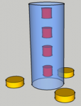
I have 10 objects that I need to locate in a 3D plane. I want to use 3 receivers or similar to triangulate the 3D position of each object, each of which can be emitting some sort of wave/ signal. The range is about 0.1m to 1.5m, and I would like the accuracy to be within a few cm.

An ultrasonic pair simply hits an object and bounces back, but as I have 10 (which are not visible i.e. walls / material obstructing view) it is impossible to use infrared or 'line of sight' communication.

Any ideas on what technology, if any, can be used to determine the distance between two electronic circuits (ignore the '10' figure for now)?
Maybe measuring signal strength could be one approach; this may be in-accurate, especially with an unknown number of obstacles in the way.

Thank you in advance
 
Last edited:

MartinM57

Moderator
3D plane? You mean 3D space?

I have no idea how to do this at the moment ... not enough detail - what are the objects, what are they emitting/can they emit, what obstacles, are they moving etc.

If the obstacles affect signal strength in an unknown way, then I can't believe measuring signal strength is the way to go.

Unless this is top secret and/or you want to make a $billion out of it, tell us more...
 

Denzel

Senior Member
3D space, excuse my terminology.

The objects are about 3cm*2cm*as flat as possible (L*W*H). The question is regarding what can they emit that I can measure? i.e. they don't exist yet until I can find a suitable technology. They are moving but only +/- 3cm every few seconds, readings only need to be taken every 5 or so seconds, even minutes if I have to. I am not trying to determine speed.

They will be covered by material and sit in a line on an large object that behaves much like a snake. lets just say I'm trying to measure the articulation of something that behaves like a snake, with a Tshirt on! so the only obstacles will be an unknown number of layers of material / folds in material.

Walls are not involved at all :p
 

Denzel

Senior Member
I also thought about putting a magnet on the object and using a hall effect sensor or similar, however it would be impossible to locate 10 magnets
 

MartinM57

Moderator
Have you thought about anything that might feasibly work? I don't think I can, but the Brains Trust here will have a go I'm sure. I'll watch with interest....;)
 

hippy

Technical Support
Staff member
So, to paraphrase and simplify, you have two PICAXE, each inside their own box ( which they cannot see out of, cannot ultrasound or IR out of ) and each needs to determine how far and in what direction the other is from itself ?

It looks to me that each will have to know where they are themselves, and each will have to receive information from the other saying where they are.

If you modelled / role-played this with humans in large cardboard boxes they would need a GPS, have to read markings on the floor, or know their positions by dead reckoning from known starting positions, and could shout or radio their positions to others.

I would expect a PICAXE solution to be the same.

If the boxes are coupled together it may be possible to use different information, such as reading the angle of any tethering bar. It may not be necessary to even know absolute positions.

Having re-read the original post; you may be saying that this 'snake of people in boxes' doesn't need to communicate amongst itself, but an observer ( in an equally isolating box ) needs to know where that 'snake' is. That would still be similar to the first scenario, though a one to many communication setup.

I think you need to provide more details on the precise configuration we are dealing with.
 
Last edited:

Denzel

Senior Member
Ok, see the diagram, basically three yellow base units that can receive / transmit to the red objects behind a material veil (translucent cylinder in pic). The red objects can move within the veil but will not change order. The objects do not need to communicate with each other and ideally are only transmitters, not receivers/ transceivers.

I have been reading some bluetooth threads in the forum, this looks very interesting; the only issue is can a single usb bluetooth dongle communicate with multiple bluetooth devices?

http://www.picaxeforum.co.uk/showthread.php?t=16029&highlight=bluetooth

http://www.mdfly.com/index.php?main_page=product_info&products_id=63
 

Attachments

womai

Senior Member
You could use a combination of electromagnetic waves and sound waves. "EM wave" being a fancy word for either radio frequency waves, signals through a cable, or light.

E.g. the object to be located turns on a bright light (LED) and at the same time sounds a buzzer. The receiver measures the difference in arrival time between the light and the sound, which gives the distance to the object (similar to how one determines the distance to a thunderstorm by counting the difference between flash and thunder). That would be the basic idea. Instead of the light you could also use a small RF transmitter, or - if the object to be located can have a wired cable connection to the receiver, a pulse through this cable.

The challenge is then to get it accurate. E.g. the Picaxe may have some lag between the start of the light and the start of the buzzer. But that could be calibrated out.

Another option - simpler - is to use sound pulses only. Each object could emit on a different frequency so you can distinguish them - using suitable bandpass filters for example. That way you could only measure the differences in distance to the receivers (assuming the receivers themselves can be cabled together). With two receivers that narrows the possible position of the emitter to an ellipsis (constant difference to the two focal points, with the focal points being the receivers), with a third receiver you can pinpoint the exact location. Just the inverse of how GPS works (there the satellites emit and the object to be located receives), but the same mathematics.

Wolfgang
 

womai

Senior Member
Denzel,

our postings crossed. I guess the pure acustical idea may work. You'd need to trigger on the start of the acoustic pulse - in your setup there may be sound reflections, but they will all arrives after the direct line-of-sight signal, so the latter gives you the true distance.

Sounds like an interesting setup, and a bit mysterious - can you tell us what it is for?

Wolfgang
 

womai

Senior Member
One more thing, in your sketch it looks like all three receivers will always be at the same distance to a particular object - that wouldn't be good, because then three receivers won't give any more information than just a single one. Is that really how the setup looks like? Could the receives be placed on different vertical levels?

Wolfgang
 

Denzel

Senior Member
Its a bio-mechanics project, trying to model gait wirelessly.

I am interested in this acoustic concept, and yes the 3 base units can be tethered. How can a picaxe record this time difference? surely not with a simple timer? I assume your counting a number of cycles...?
 

womai

Senior Member
Well, that now goes into the nitty gritty details :)

As a first estimate, sound travels at around 330 m/sec, so about 33cm/msec or 30 usec for a single cm. So whatever you use, to get a spatial resolution of 1cm you need a time resolution of you measurement of around 30 usec. Some external logic could help. E.g. some that would make a signal go high on reception of a signal from sensor 1, and go low on reception from sensor 2. You'd need another such circuit to cover the case that sensor 2 receives the signal befor sensor one, so a total of 6 identical circuits for the 3 receivers. The receiver (containing 2 Picaxe's each) could the measure the pulse lengths with the pulsin command. A 20X2 running at 64 MHz should easily have enough resolution on pulsin.

For the pulse measurement, you could get some ideas from a circuit I published a while ago:

http://www.picaxeforum.co.uk/attachment.php?attachmentid=3178&d=1240855790

There are a couple threads discussing it:

http://www.picaxeforum.co.uk/showthread.php?t=12263

and

http://www.picaxeforum.co.uk/showthread.php?t=12769&highlight=schematic

You could use only the two flip-flops and the XOR (i.e. omit the counter chps) and measure the resulting pulse (coming out of the XOR) with the pulsin command. A single 74HC74 chip contains 2 flip-flops, a single 74HC86 chip has 4 XOR gates, so for the 6 circuits you'd only need 6 pcs. 74HC74 and 2 pcs. 74HC86. Of course that's per object to track (assuming they use different frequencies), and does not yet show the bandpass filters. If size is an issue you could use surface mount chips (SOIC or TSSOP) or implement all of the logic in some CPLD.

In any case, rather than going for the full setup I'd start out with just one object and two receivers to prove the concept. The hardware for that won't cost the world, and you'll learn a lot (and find a lot of mistakes in the initial design :) before you commit to the full-blown solution. An oscilloscope will help a lot when troubleshooting the short pulses, making sure there are no glitches, fine-tuning the trigger level etc. Overall, looks like a fun project to me, I'm almost tempted to whack something like that together and see how well it works!

Wolfgang
 
Last edited:

papaof2

Senior Member
For a totaly different line of thought, "model gait wirelessly" sounds like an application for some I2C accelerometers and compasses, with PICAXEs to read the compass direction and accelerometer movement and send the data via 433 MHz radio.

Since the movement would probably start from a known position, the data could be processed by a PC to show the movements - with some serious programming, you could have a stick figure moving as reported by the compasses and accelerometers. Note that some of the boards offer "offset from horizontal/vertical" outputs, so you could get the angle between connected parts.

Not a cheap or simple project - Sure Electronics has serial compass boards for less than $10US each. I haven't priced their accelerometers, but they probably have something in that price range. Each board isn't that expensive, but your project would appear to need a number to be able to sense the postion of the "snake parts".

John
 

Denzel

Senior Member
My original prototype used accelerometers tethered by a big cable, which was uncomfortable but worked fine. I am currently having a rethink and may continue to use these sensors and simply transmit readings wirelessly rather than actually trying to wirelessly locate the objects on the leg; hence the bluetooth research.

Is anyone able to answer my question regarding the number of devices a bluetooth dongle/ cellphone can communicate with at once? I have read bluetooth v2.0 can handle 7, which I can deal with. But I am unable to confirm this with any other sources. I guess I could programatically disconnect and reconnect each device if need be, but this could take years to get a full reading of the leg.

I have found the bluetooth information on the forum very helpful and I am looking to buy a few sets to play around with.
Here is my idea so far, let me know what you think:

1. 7 'circuits' each with a picaxe, 2 accelerometers and a bluetooth transciever:

http://www.mdfly.com/index.php?main_page=product_info&products_id=63

placed around the legs on a tight pair of pants (Excuse the image you now have in your head)

2. A bluetooth dongle into the computer

3. Write a bit of VB or Python software to ask each 'device' for its readings then process the data received.
 
Last edited:

womai

Senior Member
In the professional world (e.g. for animated movies or for game development) such motion capture is usually done optically. I.e. the person wears black pants with bright dots painted/glued onto them, a set of cameras captures the movement of the dots, and software then calculates (triangulates) the 3D position of each dot vs. time based on the recorded videos and the known position of each camera. Professional equipment for that is amazingly expensive still, but recently some of it (at much lower price) is starting to make its appearance in gaming. Still probably more expensive than what you are about to build, but on the other hand it would be off-the-shelf.
 

MartinM57

Moderator
Do you need real time leg position viewing - if not, just make each sensor a datalogger, synchronised at the start (somehow), and download the data from each sensor at the end of the experiment and post process it
 

BillyGreen1973

Senior Member
Womai is on the right lines I think.
I know it gets away from using picaxes and turns to using the PC, but have a look at the Xbox 360 Kinnect. It has open source drives available and is already getting used for all sorts of different things.

Look here

http://kinecthacks.net/

It projects a pattern of IR dots onto whatever is in the room, and then 2 cameres can detect the position and dpeth of field of any object moving in front of it, quite cool actually.

A similar thing can be done with Wii remote controllers. Each controller has a IR camera in it (thats I2c too ;) ) and each camera can track upto 4 IR beacons (LEDS), use 2 Wii remotes set at different angles and again you can detect position and depth of field of 4 object (these could be hip, knee, ankle, toes). The Wii-motes are bluetooth as well.

Look here.

http://hacknmod.com/hack/top-30-wiimote-hacks-of-the-web/

just my 2 pence worth....
 
Last edited:

Denzel

Senior Member
Thanks for all the input! This has really opened my mind to the many different approaches.
I should have been more clear as to the reason why I am not utilising the current film-making techniques. This is a project that monitors in real-time how a person walks, wherever they go, driving, in the park, at the office etc and gives pointers about not overlocking knees for example in realtime.
 

hippy

Technical Support
Staff member
Is anyone able to answer my question regarding the number of devices a bluetooth dongle/ cellphone can communicate with at once? I have read bluetooth v2.0 can handle 7, which I can deal with. But I am unable to confirm this with any other sources.
A Bluetooth "piconet" can have up to 264 members; one master, 7 active slaves, and 256 parked slaves. Given the fast turnround and activation times you can consider them all connected at once, at smaller granularity it's one-to-one.

What a particular Bluetooth device is capable of depends on its hardware / firmware and Bluetooth stack. You probably cannot pick up any random Bluetooth radio or module and expect it to work standalone.

You could probably build a similar wireless network with XBee or even 433MHz; the difference being between those is in having to work out how to communicate with them and how to control any provided Bluetooth stack. You'll really need a Bluetooth expert who's done it to give best advice.

Another alternative may be Wi-Fi modules which can communicate with a Wi-Fi Hub or similar. Throw packets out and they should all be received on the LAN, their software sorting out arbitration and the link level.
 

Denzel

Senior Member
Thanks Hippy, good to clear that up. I have a friend who has used wi-fi with an aduino so will get him involved and bring over from the dark side. But I think I will test out the bluetooth capabilities regardless
 
Top