Displaying volts and amps via 18M2 and LCD
- Thread starter bfgstew
- Start date
Some of those.Is this circuit pie in the sky, to simple or just plain daft?
What are XMM's?
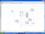
How do you think it's going to work? What is the PICAXE doing - I don't know what legs 4 and 7 (latter always connected to ground, is that what you want?) of the PICAXE do
XMM4 has its + and - connections both connected to ground - it will read 0 all the time
R3 is between the 18v (max I presume) rail and ground and will draw I = V/R = 18/0.47 = ~ 36Amps from your supply. I suspect something will blow well before your motor(?) turns
")
You might be on the right lines for voltage - potential divider into PICAXE ADC to measure voltage and display it
For current, you normally put a small resistor in series with the load - easier on the low side - and measure the voltage across it (PICAXE ADC, maybe) and turn it into current with some maths in your program
The resistors used in voltage divider for voltage measurement are too large for accurate measurements.
I would separate the high voltage and picaxe voltage with an op-amp, unity gain for voltage reading; and some gain to match the range of currents measured. Also, be aware if you use a low side current measurement (see post #2) you will need a high power resistor.
I would separate the high voltage and picaxe voltage with an op-amp, unity gain for voltage reading; and some gain to match the range of currents measured. Also, be aware if you use a low side current measurement (see post #2) you will need a high power resistor.
But XMM2 is measuring the current for you. Are these XMMs some sort of "probes" that livewire uses to tell you what voltages and currents are in the circuit - or are they real physical things you are going to use?For current, you normally put a small resistor in series with the load - easier on the low side - and measure the voltage across it (PICAXE ADC, maybe) and turn it into current with some maths in your program
<<Displaying volts and amps via 18M2 and LCD>>Where's the LCD?
bfgstew
Senior Member
I must apologise for the vagueness of info...................I am going to put it down to having a cozy night with half a bottle of rather nice single malt, my imagination ran off on some tangent and posted this, and have just remembered.......................
Now the idea is to have 2 ADC channels,1 to read volts and the other, amps from a small PSU I am making (works well with 18V max output and 3A max output), this is to be fed to a 16 X 2 LCD display.
Working the maths is reasonbly easy (ish) so no worries on that part, simple voltage divider to get the volts reading is easy. The hard part, and this is where the whiskey came in, is getting the ADC channel to read the amps. Now surfing the net, there are hundreds and thousands of solutions, ranging from, the simple to the extreme. I would like the simplest method of safely and reliable reading 0A to 3A max into ADC, then with simple math to convert to send to an LCD.
The XMM on livewire are virtual multimeters, I was trying in my stupor to come up with some wonderfully easy way of doing the above!!!!!!!!!! (can we have a hang head in shame emoticon please).
Moral of story, dont design electronics when enjoying a few wee drams.........and defo dont post on forum, unless you want everyone to have a good chuckle at your expense.........
OK so hopefully we are now on the right track regarding this thread...................suggestions, ridicule, abuse are all welcome as I am off for some nice strong coffee and some bacon butties.
bfgstew
Senior Member
Ok, with a bit more studying, I came across this little circuit for measuring current and then into an ADC channel, seems fairly straightforward.
So can the same be done with voltage, with a slight alteration on the input side using 2 resistors to form a voltage divider?
I want to be able to use the 3 spare pins on the 18M2 LCD driver board
So can the same be done with voltage, with a slight alteration on the input side using 2 resistors to form a voltage divider?
I want to be able to use the 3 spare pins on the 18M2 LCD driver board
BeanieBots
Moderator
That is a VERY ideal circuit which will work in theory but might give you some issues in practice.
You might want to add some 'slugging' to reduce spikes, especially if measuring motor currents.
An RC between the sense resistor and a cap across the op-amp feedback resistor would be a good start.
The op-amp is shown as using single rail. No op-amp is perfect and even one's which claim to work from a single rail cannot get right down to 0v.
Either give it a negative rail or put a diode (or two) in series with the op output (anode to op-amp) and a resistor (~1k) between cathode and 0v. This will give a small offset between op-amp output and feedback enabling the output to go lower than the lowest the op-amp output can go. (ie right down to 0v rather than just a bit above 0v).
For voltage, do the same but replace r-sense with a much higher value to make a potential divider with values to suite whatever voltage you need to measure.
If you use a quad op-amp package you will some op-amps left over to make into offsets if you want.
For example, measuring a 12v Pb battery, you only care about a range of 10v to 15v. ie a 5v range rather than a 15v range which gives you much better resolution.
Hi Stewart,
It depends on what resolution and accuracy you require (they are not the same thing), but IMHO there is not too much wrong with the Embedded Lab idea, or even your original scheme. It's basically just a matter of Ohm's Law....
But firstly, a 100k + 10k voltage divider is quite acceptable to use with a PICaxe A/D input, but preferably put a small capacitor (~1nF - 100nF) from the A/D input(s) to ground. Secondly, most "single rail" OP-amps can work with their inputs biassed as low as 0 volts (technically, they use PNP input transistors, so Vb can equal Vc and = 0 volts). Also their output voltage can get close to 0 volts, at least for the amount of current required to drive a PICaxe A/D input.
But do you even need an Op-Amp? A basic PICaxe can resolve its input level to within 2mV (1024 levels with a 2 volt reference), so for 1% resolution (20 mA / 2 A) the current-sensing resistor only needs to drop 200 mV, i.e. 0.1 ohm at 2 amps, and dissipate about 400 mW. For lower dissipation and/or higher resolution then an Op-Amp could be used.
However, I do have two "objections" to the Embedded Labs proposal. Firstly, their coil of wire basically appears to be an (air cored) inductor, so not very suitable if any ac is present ! That can easily be solved by winding it "bi-filar": Either wind it with twin cores and join one pair of ends together, or simply fold the wire at its centre before winding.
Secondly, Copper wire has a very significant (positive) temperature coefficient. But a PICaxe is an ideal vehicle to measure the "local" temperature (perhaps even "on-chip") and then calibrate the current accordingly. Alternatively, use proper "resistance" wire, which has a near-zero temperature coefficient and a usefully higher resistance value per unit length. But it can be less easy to solder than copper wire.
Whatever method you choose, a Google for "Wire Data" (Copper, Nichrome, etc.) to find the resistance and tempco characteristics of suitable gauges (swg/awg or mm diameters) may prove rewarding.
Cheers, Alan.
bfgstew
Senior Member
Many thanks for your input chaps.
Alan, if I could get away with not using op-amps then that is the way I want to go. Resolution is not critical, just need to get to + or - 0.1V and the same with A, if I can get it slightly lower then even better, say to + or - 0.01V and again, the same with A.
I will put something together on some breadboard and see what conclusions I come up with before putting on a board.
Hi bfgstew,
' you given me an idea to try some thing similiar soon too lol.
have to agree alot with AllyCat
although i have used a bit of telephone wire for a shunt but with a decent op amp lol.
for a bit more resolution although you would loose a couple of volts
aftr a bit maths this is what you get with a 0.66 ohm resistor.
3A .66ohm(5.94w) 1.98v @2vRef 990 *10/33= 300
2A 1.32v@2vRef 660 *10/33= 200
0.02A 0.0132@2vRef 6 *10/33 = 001
so perhaps good be tweaked to get 0.01 resolution
Last edited:
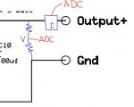
I made this one for my power supply, 30V and 3A max. The current measuring resistor, 0.47 ohm, was part of the power supply circuit. The voltage divider resistors were extra.
View attachment VA meter for bench supply.bas
I included a max current monitor.
Derek
View attachment VA meter for bench supply.bas
I included a max current monitor.
Derek
does it matter what the the sense resistor is made from?
From my experiences with stepper controller, its was best to avoid inducting resistors like wire wound etc, carbon film or alike should be used.
however that point aside, i have been toying with adding a battery level monitor to my macro rail if i have to build a new main board to engineer out the issues i have been having, but adding the sense resistor in could be tricky. i would have to add between the battery and the board (in the wire somewhere), which i presum would not matter.
battery is rated for 7.2, but i have seen with the multi meter 7.6 while the system is running, it only rated for 2.5Ah, but persume it could deliver more if needed (although i doubt the entire circuit will draw more than 1). the new design has a 5.5k and 10k potential devider across the battery rails to keep it with the 5 level of the regulated side of the circuit. would it also matter where on the 0v rail you took your adc readings from, run out of line on the connector so it would be handy to take the reading from the main board
Hi Stewart,
Ten-bit A/D conversion can resolve to about 0.1% (20 mV/ 20 V) so it's mainly a matter of getting the divider chain resistors correct. However, if you want/need the PICaxe to perform any internal calibration corrections (including CALIBADC) then division is generally limited to one byte or around +/- 0.4% accuracy. But various workarounds are possible such as replacing division with * and ** , or by using a "double-word" divison routine such as mine.
There are several reasons to try to keep the voltage drop across a current-sense resistor as small as possible. Firstly the power dissipated, it's not just "wasteful" but can be "inconvenient" to dispose of and a potential cause of errors (tempco and/or ageing of the components, etc.). Then the voltage is potentially "lost" from that applied across the load, although it can of course be calculated and even corrected by the PICaxe or a "differential" supply regulator control circuit.
Personally I would aim at a maximum drop of about 0.5 volt for a 2 A power supply. Then the PICaxe can use its internal 2 volt Fixed Voltage Reference and 10-bit A/D converion will fill just the low byte with an 8-bit data value.
There are various "tricks" to increase the resolution of the A/D conversion process. I have still to try most of the following ideas; it's one of the reasons I haven't fully documeted my "AA battery tester" (e.g. in post #26 here) as a finished project yet. Basically the methods rely on there being a small amount "noise" on the A/D converter input and then taking the "average" of multiple A/D readings (in an extreme case one might sum 64 x 10-bit A/D conversions to produce a "16-bit" result). In some cases, the noise might be "accidental" (or inherent) but for my applications it will be introduced intentionally. What I have in mind is basically to connect a high value resistor from a spare PICaxe pin to "mix" (add) a signal onto the A/D input(s). The "noise" will have an amplitude comparable (slightly higher) than the A/D resolution (step size). Perhaps in the form of a ramp/sawtooth waveform generated by a PWM output, or the D/A output pin, or maybe the "touch" oscillator, or just a "background" software task.
Cheers, Alan.
Last edited:
Current monitoring is of interest for charging, fault or motor stall detection, bench power supplies etc. But not so much value for purposes of battery health monitoring I would think? Simple voltage monitor would suffice for that purpose, I'm sure.i have been toying with adding a battery level monitor to my macro rail .... but adding the sense resistor in could be tricky.
Might be a misunderstanding there; 2.5Ah is the capacity, the size of the bucket. You can pour the content out fast - 5A - or slow - 0.5A - but only for so long in either case; half hour or five hours respectively. There is no 'more' to be had from the bucket.it only rated for 2.5Ah, but persume it could deliver more if needed
The battery will have some design maximum current limit before bad things happen - boils up or terminals melt off etc. - but that would normally be much larger numbers, tens or even hundreds of amps.
Assuming the low side current sensing resistor is "inside" the power supply rather than part of your circuit i.e. imagine your power supply has +ve and -ve 4mm sockets on the front panel and the current sense resistor is inside the case between the -ve socket and the "real" earth.
Your -ve 4 mm socket is only therefore at earth potential when no current is flowing in your external circuit - not useful - and the more current that flows in your circuit the more the -ve 4mm socket rises above earth (since the more the current is flowing, the more voltage is developed across the resistor and you are measuring that voltage to determine what that current is)
So now you have another circuit fed from another supply that has its ground at actual earth potential (since it doesn't have a low side current sense resistor)...
...and you want to have say a serial link between your two circuits
...so some smart alec comes along and tells you that must join the "grounds" together
So you do...and you've potentially (haha - but it can happen) just shorted out the current sense resistor by connecting its "top end" to the real earth on the other supply - so it gets no current flowing through it, no voltage developed across it and your current meter display drops to zero. Oh dear.
...which is why high side current detection is better as the resistor just has the effect of dropping the voltage to the load slightly rather raising the ground potential of your circuit above earth
But high side current detection is another ball game:
- you need a differential measurement of the voltage across the resistor (just like when it's low side, but conveniently one side is actually at earth potential) but both ends are near to the supply voltage, so you're now into differential amplifier circuits with so-called "common mode rejection"
- or you use a high side current sensing chip like the ACS712 I mentioned above that converts the current flowing through it into a voltage that you simply measure with a PICAXE ADC input...but that suggestion seems to have fallen on stony ground.
Phew, what a lot of words.
Your -ve 4 mm socket is only therefore at earth potential when no current is flowing in your external circuit - not useful
- and the more current that flows in your circuit the more the -ve 4mm socket rises above earth (since the more the current is flowing, the more voltage is developed across the resistor and you are measuring that voltage to determine what that current is)So now you have another circuit fed from another supply that has its ground at actual earth potential (since it doesn't have a low side current sense resistor)...
...and you want to have say a serial link between your two circuits
...so some smart alec comes along and tells you that must join the "grounds" together
So you do...and you've potentially (haha - but it can happen) just shorted out the current sense resistor by connecting its "top end" to the real earth on the other supply - so it gets no current flowing through it, no voltage developed across it and your current meter display drops to zero. Oh dear.
...which is why high side current detection is better as the resistor just has the effect of dropping the voltage to the load slightly rather raising the ground potential of your circuit above earth
But high side current detection is another ball game:
- you need a differential measurement of the voltage across the resistor (just like when it's low side, but conveniently one side is actually at earth potential) but both ends are near to the supply voltage, so you're now into differential amplifier circuits with so-called "common mode rejection"
- or you use a high side current sensing chip like the ACS712 I mentioned above that converts the current flowing through it into a voltage that you simply measure with a PICAXE ADC input...but that suggestion seems to have fallen on stony ground.
Phew, what a lot of words.
bfgstew
Senior Member
Ok, have had a go at calculating the divider for measuring voltage (simple I know for most, not for me!)
So R1 = 10K
R2 = 3.3K
so should give me a sweep from .25mV @ 0v up to 4.46v @ 18v (PSU gives output of 0 to 18v)
I did worry about amps, so did another calculation and my findings show I should be OK - @ 0v = 75uA and @ 18v = 1.353mA
Do these sound feasable and correct to you?
Now to work out the current measuring bit...................!!!!!!!!!1
bfgstew
Senior Member
Martin, far from it, I have considered it and if I had a spare £20+ I would use them, but I haven't and so I would like to explore a simple method of measuring the output voltage and load of a PSU currently being constructed. I have several 16X2 LCD units and thought it would be a neat idea to use them as the 18M2 used to drive them has 3 spare pins. Once I have got the dividers set up correctly, the next step is to make sure what you have said doesn't happen, there is no point in building something the first time you switch it on and use it, the magic smoke escapes. The terms high side and low side does confuse me slightly so off to google it and cram some more info in the old grey matter.............but that suggestion seems to have fallen on stony ground
Thanks for the guidance and advice, it doesn't fall on stony ground, honestly.
bfgstew
Senior Member
Ah I see what you mean now about high and low side, makes sense now...................DOH.
Had a scout round the net and found this little chap, now I know there are plenty of fake stuff out there but for £3 it may be worth a punt?
Had a scout round the net and found this little chap, now I know there are plenty of fake stuff out there but for £3 it may be worth a punt?
Hi Stewart,
It's probably "genuine", but is going to come in from China so will probably take a few weeks to arrive.
Also available on ebay from various suppliers (or at least various usernames - the listings are often suspiciously similar) at £2 or less (again from China or HK of course). If you're patient, you just takes your choice. And if problems arise, most suppliers are very accommodating (to protect their feedback reputation) and you usually have the Paypal guarantee as well.
EDIT: Ah, I see it's also available from some UK suppliers (via ebay) at around £4 if you're in more of a hurry.
Cheers, Alan.
Last edited:
bfgstew
Senior Member
Right, I now know what I am going to do.
Current sensing module from China.
Make a simple voltage divider for voltage reading, (10K for R1 and 3.3K for R2)
Both going to individual ADC pins on 18M2.
Now, I am going to ask what may seem an obvious question, but regarding Martins earlier pointers on correct location for current sensing etc etc.
This is the PSU circuit in question, courtesy of Downwind, now where do I connect the current sensing module and the voltage divider to avoid any unpleasantness....????
View attachment 2010-01-25_021539_LM_723_variable_supply_schematic_in_PDF.pdf
Many thanks in advance
Stewart
The next challenge is you also need a good 5v supply for the PICAXE and the diaplays from within the power supply if it's all self-contained - it obviously can't come direct from the +ve output as that's variable (and less than 5v sometimes so you can't use a regulator from it) so you'll need some sort of low power 5v regulator fed from pins 11/12 on the '723
What's the voltage at pins 11/12? It might be quite high (more than 20v) so someone will need to spend a few moments finding a 5v linear regulator that can take a constant >20v input and take the power dissipated in it, without getting too hot, due to the current drawn by the PICAXE and the LCDs (which shouldn't be much)
..a suitable linear regulator should be fine, no need to go looking for a SMPS design yet
Hi Stewart,
Hmm, I've seen that PSU design before (on this forum) and surely there must be a better one around.
Firstly, just one 2N3055 will do the 2 (or even 3) amps that you quoted above. But my main "objection" is that any decent General Purpose or "bench" power supply should allow the output voltage and/or current limit to be set to quite low values. I'm not sure what the minimum output voltage is, but it certainly can't be "increased carefully up from zero". And the minimum current limit is certainly more than one amp (and "infinity" amps at the other end of its "current limit" pot).
But the design of good bench supplies is not easy (one reason why they're expensive) so I'm sorry that I don't have a "better" design to offer you off-the-shelf. What are you actually planning to use the supply for? What are your minimum output setting requirements (i.e output adjustment ranges)?
Cheers, Alan.
bfgstew
Senior Member
Hi Alan, minimum voltage is 2V and using a 10 turn pot I can scale up to full voltage 28V nicely.
Its a basic bench supply, just so I have one that I can test motors, relays and other stuff, nothing critical.
I agree it is a bit basic but it is over 20 years old the design, but it works.
Its a basic bench supply, just so I have one that I can test motors, relays and other stuff, nothing critical.
I agree it is a bit basic but it is over 20 years old the design, but it works.
Hi Stewart,
Perhaps I was a little "unkind" about the LM723 Power Supply, at least for testing fairly "indestructable" components such as motors and relays. I believe the original design was intended to deliver about 10 Amps, so it can be greatly simplified and cheapened by using a single 2N3055 for 3 Amps.
A minimum of 2 volts output meets most requirements, but even 2 volts can deliver a LOT of current into a short-circuit or very low impedance! The "current limiting" part of the circuit is basically intended to protect the power supply itself, NOT the load it is driving. So it's unlikely to "prevent the magic smoke escaping" if a PICaxe is wired backwards across its output terminals, for example. Both of these limitations could possibly be fixed with the addition of just a handful of cheap components, but I'm always reluctant to suggest modifications to hardware (or software) without actually building/testing it.
It is of course quite complicated, although the major costs are probably for the transformer and the PCB (I haven't checked if the Op-Amps are "exotic" and/or expensive). As such, it might be quite difficult or impossible for a relative newcomer to fault-find, if their version doesn't work for any reason.
I certainly wouldn't discourage anybody who wants a decent "Lab." Power Supply from building that design, but I do have two minor reservations: Firstly, the only integrated circuits used are "simple" Op-Amps; there are probably now simpler designs available using an appropriate "dedicated" PSU chip. Secondly, if you happen to need (say) 3 volts output at 3 Amps, then the series transistor must dissipate about 80 watts, which needs a BIG heatsink. I think a versatile, modern design would probably combine a (variable) Switched-Mode Power Supply (in place of an enormous heatsink) with a susidiary linear output stage to accurately regulate, filter and current-limit the output voltage.
Cheers, Alan.
Perhaps I was a little "unkind" about the LM723 Power Supply, at least for testing fairly "indestructable" components such as motors and relays. I believe the original design was intended to deliver about 10 Amps, so it can be greatly simplified and cheapened by using a single 2N3055 for 3 Amps.
A minimum of 2 volts output meets most requirements, but even 2 volts can deliver a LOT of current into a short-circuit or very low impedance! The "current limiting" part of the circuit is basically intended to protect the power supply itself, NOT the load it is driving. So it's unlikely to "prevent the magic smoke escaping" if a PICaxe is wired backwards across its output terminals, for example. Both of these limitations could possibly be fixed with the addition of just a handful of cheap components, but I'm always reluctant to suggest modifications to hardware (or software) without actually building/testing it.
Yes, that's much more what I would call a Bench/Laboratory Power Supply design. However, the schematic diagram doesn't have any component values marked, so it's not immediately obvious exactly how (or how well) it works. It would take a considerable time to analyse the full design from the Parts List (and ideally build it) to determine whether it is just a "competent" design or a "good/excellent" one.I came across this PSU, it seems a bit more advanced than the one I have built, any advice on this one?
It is of course quite complicated, although the major costs are probably for the transformer and the PCB (I haven't checked if the Op-Amps are "exotic" and/or expensive). As such, it might be quite difficult or impossible for a relative newcomer to fault-find, if their version doesn't work for any reason.
I certainly wouldn't discourage anybody who wants a decent "Lab." Power Supply from building that design, but I do have two minor reservations: Firstly, the only integrated circuits used are "simple" Op-Amps; there are probably now simpler designs available using an appropriate "dedicated" PSU chip. Secondly, if you happen to need (say) 3 volts output at 3 Amps, then the series transistor must dissipate about 80 watts, which needs a BIG heatsink. I think a versatile, modern design would probably combine a (variable) Switched-Mode Power Supply (in place of an enormous heatsink) with a susidiary linear output stage to accurately regulate, filter and current-limit the output voltage.
Cheers, Alan.
bfgstew
Senior Member
We could go really over the top and construct this one..........................
View attachment 3005X_schematic.pdf
Would be nice though?
View attachment 3005X_schematic.pdf
Would be nice though?
JimPerry
Senior Member
Don't trust any circuit diagram that labels a mains transformer as TransistorWe could go really over the top and construct this one..........................
View attachment 16319
Would be nice though?
bfgstew
Senior Member
OK, I have got my LCD up and running and have connected the output of a 10k pot to the ADC channel C.2 on the 18M2+ driving the LCD (Parallel interface). Now all I am doing at the moment is trying to work out the math to convert the readadc10 value generated by C.2 into an accurate readout from 0 to 30 volts in 0.1 steps, it would be superb if I can get it down to 0.01 steps but let's take one step at a time. The other part of the display is having it show as 12.47v for example, rather than 1247. I have tried for a few hours last night to make a start but I just cannot get my head around the math on this.
As I say this is purely to get the math and my head together, the final circuit is going to go through a voltage divider to give as near as possible a 0 - 5v sweep, so the code will need tweaking later on the final build.
So
do
readadc10,w0
let w0 = w0?????
????????????????
;send result to LCD
loop
Can someone help/point me in the right direction.
Thanks in advance
Stewart
Hi Stewart,
Working to one decimal place is MUCH easier than two, for numerous reasons. Basically, you need to do the calculations in "deci-volts" (i.e. tenth's of a volt) so your "full-scale" value should be about 300. Then, as e says, you just need to divide by 10 for the "integer" part (/) and then "print" the "remainder" (//) after a decimal point.
As far as the "maths" is concerned you basically need to multiply (the A/D value) by the voltage divider ratio (e.g. multiply by 11 if you have a 10k + 1k chain) and multiply by the reference voltage, e.g. 50 if your A/D converter has a 5 volt (50 deci-volts) reference, and divide by the full-scale value of the A/D converter (e.g. 1024).
However, you must be careful to avoid overflows (>65,535) and truncation (loss of accuracy) with the integer maths. So you need to multiply and divide in the correct sequence and probably split the division by 1024 into two stages. For example if you have an A/D value up to 1023 (10 bits) you can multiply it by the 50 (reference volts), then divide by 16 (part of the 1024), multiply by the 11 (divider ratio) and finally divide by 64 (the rest of the 1024).
Alternative methods are to replace the division by the ** operator (which basically multiplies by a variable/constant and divides by 65,536 at the same time), or use my double-word division routine linked earlier in the thread. But let's take one thing at a time.......
___
Actually, the third PSU diagram you linked above isn't ludicrously complicated, but there are a number of "loose ends" so I wouldn't actually try to build it. Although it has 4 x 160 volt, 10+ amp output transistors, the reservoir capacitors suggest that it delivers a maximum of about 30 - 40 volts at around 5 Amps? Certainly the power rating of the current-sensing resistor limits it to 10A. I quite like the "brute force" solution of two relays selecting 4 taps on the transformer (agreed, not a transistor) to reduce wasted/inconvenient power dissipation.
But (particularly in view of the thread title) perhaps its metering arrangements are the most interesting (and puzzling). Current is monitored by a "high side" resistor, however it then appears to use a "positive earth" arrangement (but their use of Earth symbols does seem to be rather cavalier). However, the voltage divider appears to be 2M + 10k, so the A/D input would be no more than ~150mV. Then both (V and I) signals pass through 1 Mohm resistors before reaching the A/D inputs.
The display itself is also interesting. The "backlight" appears to be fed from 10 volts though only about 15 ohms, and all the segments driven individually? I wonder if it's a Vacuum Fluorescent display, or just a rather ancient 7-segment LCD + LED (or filiament lamp) type?
Cheers, Alan.
Hi bfgstew,
readadc10 returns a value of 1023
so we get 0.01 resolution upto 10v ie. 10.23v
for 30v the resolution is in steps of 0.03 ie 1023 x3 =30.69
perhaps also have a look at some examples here.
http://www.picaxeforum.co.uk/showthread.php?23377-Voltage-Divders-Made-Easy-!
today building supply is quite questionable
I may build 1 in the future only because i have some parts laying around lol.
far cheaper to buy 1 and the use the picaxe to display voltage and limit the current of the output.
http://www.ebay.com/itm/New-12A-DC-Converter-4-5-32V-OUT-0-8-30V-Buck-Power-Supply-Module-/251261015009?pt=LH_DefaultDomain_0&hash=item3a8052d3e1
just a note some of these supplys can be misleading while it may show an output of 12amps is a bit misleading.
it is probaly only rated at 100watts continuous so at 30v around 3amps is the maxium without requiring additional heatsinking.
Last edited:
bfgstew
Senior Member
Thanks marks, we seem to have success.
We will have to see when the circuit is built how well this code performs, obviously this is set with a perfect 5v Vin, just will need tweaking slightly but it does what it says on the tin, it shows a full sweep from VOLTS = 00.00 to VOLTS = 30.00 in 0.01 steps.
Many thanks again chaps, couldn't have done it without you.
Stewart
Code:
#PICAXE 18M2

symbol lcddata = pinsB
symbol rs = C.7
symbol enable = C.6
setfreq m16
symbol loopcounter = b20
symbol volts = w0


INIT:

	setfreq m16
	dirsB = 255
	low rs
	output enable

	lcddata = %00111011 : pulsout enable,16
	lcddata = %00000001 : pulsout enable,608
	lcddata = %00001100 : pulsout enable,608
	lcddata = %00000110 : pulsout enable,16

SETSCREEN:

	low rs
		lcddata = 128 : pulsout enable,1
			high rs
				for loopcounter = 0 to 15
				lookup loopcounter,("VOLTS =   .     "), lcddata
			pulsout enable,1
		next loopcounter
	low rs
		lcddata = 192 : pulsout enable,1
			high rs
				for loopcounter = 0 to 15
				lookup loopcounter,("AMPS =   .      "), lcddata
			pulsout enable,1
		next loopcounter
	low rs

MAIN:

	do
  		readadc10 C.2,volts
			Volts = Volts **64064
			Volts = Volts *30
			volts = volts / 10
  				low rs
					lcddata = 136 : pulsout enable,1
						high rs
      						for loopcounter = 0 to 1
  						BinToAscii w0,b10,b11,b12,b13,b14
					lookup loopcounter,(b11,b12), lcddata
				pulsout enable,1
			next loopcounter
		low rs
			lcddata = 139 : pulsout enable,1
				high rs
      				for loopcounter = 0 to 1
  						BinToAscii w0,b10,b11,b12,b13,b14
					lookup loopcounter,(b13,b14), lcddata
				pulsout enable,1
			next loopcounter
		low rs
loopMany thanks again chaps, couldn't have done it without you.
Stewart
Hi Stewart,
Check the number of program bytes in my version compared with yours.Code:Volts = Volts **64064 Volts = Volts *30 volts = volts / 10 [/QUOTE] Hmm, a little complicated. The **64064 is basically a "calibration" stage, multiplying by about 0.977 (i.e. 64064 / 65536). It allows a very high resolution, but only up to * 0.99998 (i.e. 65535 / 65536), it won't work if you need to calibrate any higher. So I would normally use 32032 and multiply by 2 somewhere else in the calculation. Your next two lines are just multiplying by 3, so your final resolution must increase also in steps of 3 . It's where I would put in that extra *2 , i.e. volts = volts * 6 . For the "printing" part, I'd use something like the following (not fully tested as I don't have any hardware set up at the moment): [code] Volts = Volts ** 32032 ; Adjust up or down for final calibration Volts = Volts * 6 ; "Magic number" related to the voltage divider and calibration factor, etc. :) ; Set (or leave) the cursor at the start of the numeric field. (##.##) High rs BinToAscii Volts,b10,b10,b11,b13,b14 ; Note the exact sequence of byte variables b12 = "." for bptr = 10 to 14 ; Point to variables b10 to b14 in sequence lcddata = @bptr ; Read the ASCII character pulsout enable,1 next bptr
Cheers, Alan.
bfgstew
Senior Member
Thanks for the pointers Alan, I did have a comparison with your snippet and it is only 70 odd bytes smaller, but it did get a bit garbled on the screen, so it will need some work to get it showing correctly, the calibration value works just as well so am incoperating it into the final code.
Now to get building, I am going for the second PSU as it comes with a layout for a PCB so I can get that etched next week while I am waiting for the few odd components I need.
Watch this space.......................I may need your help again......................
Now to get building, I am going for the second PSU as it comes with a layout for a PCB so I can get that etched next week while I am waiting for the few odd components I need.
Watch this space.......................I may need your help again......................
Hi Stewart,
You should be able to remove some of the trailing <spaces> (and the ".") from your LOOKUPs to get the formatting correct (and save some more program space).
Also, changing the following two lines (it should be obvious where) could* improve the accuracy:
*EDIT: With hindsight, only the +3 (or +30) for the "rounding" will help at all, since (as said by marks earlier) there can be only 1024 possible values (typically 30mV apart). However, it may be worthwhile accumulating (adding) the results of 2, 6 or 10 consecutive A/D conversions (all numbers which already appear as multipliers in the calculation) to increase the apparent resolution.
As I mentioned above, my long-term aim is to experiment with adding some "dither" to the A/D input(s) to increase the resolution of my voltage measurements.
Cheers, Alan.
You should be able to remove some of the trailing <spaces> (and the ".") from your LOOKUPs to get the formatting correct (and save some more program space).
Also, changing the following two lines (it should be obvious where) could* improve the accuracy:
Code:
Volts = Volts * 60          ; And Optionally, + 30 to "round up" the original integer value

BinToAscii Volts,b10,b11,b13,b14,b12 ; b12 (millivolts, but not accurate) will be overwritten by the "."As I mentioned above, my long-term aim is to experiment with adding some "dither" to the A/D input(s) to increase the resolution of my voltage measurements.
Cheers, Alan.
Last edited: