Direct RS232 connection 08m2 14m2

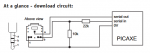
I am thinking of a project to use a terminal to send keyboard presses to Picaxe for controlling various pin states, and maybe eventually sending sensor data from picaxe back to the terminal. Is it ok just to use the standard serial circuit but instead of using the Axe026 cable connect direct to a DB9 serial cable? Or does the Axe026 have level shifters that are needed? The reason I want to connect without using a cable is that I want to build the project into a box that connects via a DB9 socket and power the picaxe from the serial port. I will be using a 08m2 or 14m2. I am aware of RS232 to TTL level shifter breakouts so if needs be I can use one of those, but I was not sure if it is needed if using the suggested recommended serial circuit.
 

erco

Senior Member
Sure, if you have a real serial port you can wire up your 3 Picaxe connections plus power thru a DB9 or any connector you like. I use 3-wire servo extension cables for programming all the time. Of course you could also get power thru a USB cable. Skip the AXE027 cable, build your own cp2102 or ch340 USB adapter into your project, then connect to your computer using a USB extension cable.
 
Yes the 22k and 10k resistors form a voltage divider if I’m not mistaken, but I wondered if the AXE026 and AXE027 were doing anything inside the connector to reduce voltage too. Anyway thanks for your help, seems safe to proceed - now I just have to learn about serial on picaxe :)
 

Buzby

Senior Member
No !.

The The 22K is a current limiter, needed if the serial signal is 12v , as used on some Old Skool RS232 devices.

The 10K is just a simple pull-down, needed to stop the PICAXE going into 'download mode' continuously.

download.PNG
 

AllyCat

Senior Member
Hi,

Yes, but if the PC is delivering a "Real" RS232 output (pulling the input down to perhaps -10 volts) AND you are using any ADC inputs (i.e. READADC{10} ), then it's better to use the "Enhanced Serial Download Circuit" (or similar) shown on page 45 of the online PICAXE Manual 1 , to prevent a (negative) current flowing in the PICaxe's Substrate diode.

Cheers, Alan.
 

AllyCat

Senior Member
Hi,

There are two distinctly separate issues; the Polarity of the serial communications (PICaxe and "real RS232" use Idle Low) and the voltage Levels of the signal, particularly the negative voltage from (only) real RS232. A "RS232 to TTL Level Shifter" or Phil's circuit above do both of these functions, but in most cases neither is essential for a PICaxe (except notably using HSERIN with M2 chips). Also it may depend if you want to use specifically the PICaxe Program Editor Terminal Emulator or any generic "Terminal {Emulator}" and/or communicate via (only) the Programming I/O interface pins (i.e. SERRXD and SERTXD) or any other of the PICaxe pins (i.e. SERIN/OUT, etc.).

Cheers, Alan.
 
I see, well I will be using an older computer (possibly a few different ones) and will just be using the rx/tx pins, I think I’ll just add a ready made rs232-ttl level shifter to be on the safe side and also to make construction easier (idiot proof!) thanks all for the input and ideas.
 

PhilHornby

Senior Member
I think I’ll just add a ready made rs232-ttl level shifter to be on the safe side and also to make construction easier (idiot proof!) thanks all for the input and ideas.
That might interfere with your earlier requirement...
I want to build the project into a box that connects via a DB9 socket and power the picaxe from the serial port
The first ready-made level-shifter I came across online (the Sparkfun version), powers the level-shifter from the "TTL" side (i.e. the other way round).

(In my Growatt project, I found an unexpected +9V wrt GND, on the RI pin It supplies enough current to operate a HC-12. I don't know what was present on PC ports - or if there was any kind of standard)
 
So you mean the shifter will power the picaxe from the 5v VCC line of the shifter? I thought the level shifter gets its power from the RS232 port, so if that is the case then it would be for all intents and purposes the same thing - basically I’d build the level shifter and picaxe in a box and power from the rs232 - or am I misunderstanding?
 

PhilHornby

Senior Member
So you mean the shifter will power the picaxe from the 5v VCC line of the shifter?
No.
I thought the level shifter gets its power from the RS232 port
No.

For the particular Sparkfun product I linked to, it says:

Shifter SMD is powered from the target application and can run at any voltage! That's right - power the board at 5V and the unit will convert RS232 to 5V TTL. Power the board at 2.8V and the Shifter board will convert RS232 to 2.8V CMOS TTL
(Though other products may be available that work differently).

Cleverer people than me, may be able to suggest how to harvest power from the RS232C line (if no convenient signal like my Growatt's Ring Indicator (RI) is present. The old Serial Mouse interface I linked to, already does this to generate the negative-going signals that the RS232C standard specifies.

(As @allycat pointed out, you may be able to get away with a much simpler interface - it depends how picky the connected RS232C device is...)
 

inglewoodpete

Senior Member
I started with PICAXEs using the AXE026 - a straight-through RS232 cable plugged into my computer's H/W serial port. (As an aside, I have replaced the motherboard twice since then and have insisted on them having H/W RS232.)

The ONLY criteria that I use when deciding whether to use TTL or RS232 is "Is this project going to use ADC?

I use the 10k + 22k serial input circuit on all my microcontroller projects, including two that use PIC32s, operating on 3.3volts
 
My goal initially is to turn on/off some LEDs from the computer with a key press lets say 2 LEDs, the Picaxe will maintain the state until told to change from serial, also the Picaxe will send “LED1 On” / “LED1 Off” as appropriate. I already loaded the serial example in PE6 to the 08m2 and connection seems somewhat working, but not sure how to proceed.
Can anyone post some examples to get me started? I want to have the baud rate at 9600.

Thanks
 

hippy

Ex-Staff (retired)
The program below should work though I admit I have only tested it on an actual 18M2.

You may need to alter the LED1 and LED2 definitions. They currently assume the two bottom right pins of the chip.

Send 0 or "0" to turn both LED off, 1 or 2, "1" or "2", to turn on just LED1 or LED2, send 3 or "3" to turn both on.

You will need to do a Hard Reset to load a subsequent program.

Code:
; #Picaxe 08M2
#Picaxe 14M2
; #Picaxe 18M2
#Terminal 9600
#No_Data

#IfDef _08M2
  Symbol LED1 = C.1
  Symbol LED2 = C.2
  Symbol TX   = C.0
  Symbol RX   = C.5
#EndIf

#IfDef _14M2
  Symbol LED1 = B.4
  Symbol LED2 = B.5
  Symbol TX   = B.0
  Symbol RX   = C.5
#EndIf

#IfDef _18M2
  Symbol LED1 = B.5
  Symbol LED2 = B.4
  Symbol TX   = C.3
  Symbol RX   = C.4
#EndIf

Symbol BAUD = N9600_8

PowerOnReset:
  Pause 2000
  Disconnect
  SetFreq M8
  SerOut TX, BAUD, ( "Ready" )

MainLoop:
  Do
    SerOut TX, BAUD, ( CR, LF, ">" )
    SerIn  RX, BAUD, b0
    SerOut TX, BAUD, ( b0, CR, LF )
    Select Case b0
      Case 0, "0" : Low  LED1 : Low  LED2 : SerOut TX, BAUD, ( "LED1=OFF  LED2=OFF" )
      Case 1, "1" : High LED1 : Low  LED2 : SerOut TX, BAUD, ( "LED1=ON   LED2=OFF" )
      Case 2, "2" : Low  LED1 : High LED2 : SerOut TX, BAUD, ( "LED1=OFF  LED2=ON"  )
      Case 3, "3" : High LED1 : High LED2 : SerOut TX, BAUD, ( "LED1=ON   LED2=ON"  )
    End Select
  Loop
 
Thanks so much hippy, I will try this out :)
Out of interest why the disconnect command in the power on reset part? Edit: Ah, to stop the chip looking for downloads which might interfere with operation.

Next goal is to read a sensor and output the value over the serial port after a request from the computer, then eventually a data logger which records various sensors and perhaps turns on devices once certain conditions are met. But I will take it step by step, I still find a lot of this stuff very difficult to learn, but I have had a few successful projects using Picaxe in the past albeit much much simpler, so hopefully I can get this working.

Edit2: I tried it and it works very well, then I made some edits so that the LEDs can be turned on and off independently as well as together, by adding a couple of extra case statements and editing a couple of the ones you posted, great stuff!
 
Last edited:

hippy

Ex-Staff (retired)
Out of interest why the disconnect command in the power on reset part? Edit: Ah, to stop the chip looking for downloads which might interfere with operation.
That's correct. Normally a SERRXD would automatically do that for you and an explicit DISCONNECT isn't needed. But because I was specifying a 9600 baud rate I used SERIN which doesn't do the DISCONNECT.

Thinking about it, as I had to use SETFREQ M8 to get 9600 baud, it would probably work with that SETFREQ M8 and using SERRXD and SERTXD. That saves some typing as well if you are sending back status reports. I'll give it a try.

I tried it and it works very well, then I made some edits so that the LEDs can be turned on and off independently as well as together, by adding a couple of extra case statements and editing a couple of the ones you posted, great stuff!
Thanks for letting us know it works. Beyond reading and sending the serial, the world is your oyster when it comes to what goes in the SELECT-CASE statement.
 

hippy

Ex-Staff (retired)
SERRXD and SERTXD worked just as well on my PICAXE-18M2 - For some reason I thought they were locked at 4800 baud but of course aren't.

And apologies for the delay in responding. For some reason I got logged out of the forum and hadn't noticed so 'new posts' weren't showing anything new !

Code:
#Picaxe 14M2
#Terminal 9600
#No_Data

Symbol LED1 = B.4
Symbol LED2 = B.5

PowerOnReset:
  Pause 2000
  SetFreq M8
  SerTxd( "Ready" )

MainLoop:
  Do
    SerTxd( CR, LF, ">" )
    SerRxd b0
    SerTxd( b0, CR, LF )
    Select Case b0
      Case 0, "0" : Low  LED1 : Low  LED2 : SerTxd( "LED1=OFF  LED2=OFF" )
      Case 1, "1" : High LED1 : Low  LED2 : SerTxd( "LED1=ON   LED2=OFF" )
      Case 2, "2" : Low  LED1 : High LED2 : SerTxd( "LED1=OFF  LED2=ON"  )
      Case 3, "3" : High LED1 : High LED2 : SerTxd( "LED1=ON   LED2=ON"  )
    End Select
  Loop
 
Yes that SELECT CASE structure is very useful, I’d never have thought of that, but now I have added a couple more CASE statements including a readadc if a key is sent over serial and a serial output of the value, really handy!

Next is to figure out a way of converting the raw adc value into real data, for example temperature or humidity or voltage etc, but for the time being still figuring out exactly the physical/electronic side of things, at present just using 08m2 but will probably use 14m2, and eventually add a wifi module to replace the wired serial connection.
I will try the revised version you posted and add back in the extra CASE statements, I think it is quite a useful general purpose serial utility, I will probably end up doing a bunch of projects with it :)

Thanks for all your help!
 

hippy

Ex-Staff (retired)
Next is to figure out a way of converting the raw adc value into real data, for example temperature or humidity or voltage etc,
That will usually depend on the sensor or signal being read but the conversion formula should be in the datasheet. Some will be linear which should be reasonably easy but others may require lookup tables and interpolation. I am sure people here will be pleased to help you out if you do need any help with that.
 
Yes I think I need to figure out what sensors I need then go from there, I was just using a simple LDR module for testing, but eventually will probably want to do temperature, voltage, humidity, and maybe other stuff too. Possibly then upon a certain value from a sensor a pin goes high, say to turn on a relay when voltage drops below a certain level, and have that send a message over serial. One end goal is a workshop monitoring system, although not as grand as it sounds, the workshop is an old caravan in the garden, that I am converting.

I was just reading in the other thread https://picaxeforum.co.uk/threads/wheres-the-wizard.31896/ about the IOT stuff, which is quite similar in principle to what I had in mind, although much simpler and just on a local point to point wifi network rather than over the internet, so I will probably look into adding a ESP wifi to serial tx/rx bridge, there is probably some existing code out there that I can adapt. There is I suppose the argument for doing it all with an ESP but I want to retain modularity and prefer Picaxe for a number of reasons. This way I could have a few different modules all using the same ESP code - a “dumb” serial over wifi basic web server thing, plug different Picaxe projects into it without having to troubleshoot too much.
 

regpye

New Member
Select Case b0 Case 0, "0" : Low LED1 : Low LED2 : SerTxd( "LED1=OFF LED2=OFF" ) Case 1, "1" : High LED1 : Low LED2 : SerTxd( "LED1=ON LED2=OFF" ) Case 2, "2" : Low LED1 : High LED2 : SerTxd( "LED1=OFF LED2=ON" ) Case 3, "3" : High LED1 : High LED2 : SerTxd( "LED1=ON LED2=ON" ) End Select
I still don't understand the process, maybe I am too dumb or something?
The structure I can see, but how it works and what makes it work I need to understand before I can successfully use it.
 

hippy

Ex-Staff (retired)
The PICAXE process has five steps -

First the PICAXE sends a ">" to the PC to tell it that the PICAXE is ready to receive a command character.

The PICAXE then executes a SERRXD ready to receive whatever character the PC sends it.

When that is received the PICAXE echoes what it received to the PC so it can check that what was received was what was sent if it chooses to.

The PICAXE then decides what to do with what it received using the CASE-SELECT and, in this code also sends a report on what the LED status is.

It then goes back to sending another ">" so the PC knows that it is ready to receive another command character from the PC.

The PC program can be much simpler, simply waiting for a ">" and then sending a command character. It can choose to check or ignore the echoed command character, can ignore any status report, skip everything until it gets a ">"character.

The main reason the PICAXE code is how it is, is so it can be tested from the Terminal window. For example -
Code:
Ready
>1
LED1=ON   LED2=OFF
>2
LED1=OFF  LED2=ON
>0
LED1=OFF  LED2=OFF
>
The reason for using " Case 0, "0" : ..."etc is that it would be usual to control from another PICAXE by using 'SerOut ... (0)' and similar to send the command code, or from a PC program using something like 'serial.write(0)', but from a terminal it's more likely an ASCII character "0"would be typed, which has a different value to zero. Using Case 0, "0" : ..." allows both to be accepted, the comma is basically an 'or'.
 
Top