Diode confusion

sid

Senior Member
Hi all,
I've made a few picaxe curcuits but my knowledge of electronics is a bit sketchy and I've come up against a problem while making a new picaxe circuit that involves a diode.
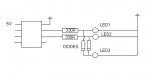
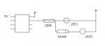
As you will see in the attached diagram the axe is powering led1 via a 330r resistor, however led2 which is being fed via a diode will not light until I disconnect led1.
I can work around this by using a spare output on the axe but I want to know why led2 won't light when led1 is lit.
As I understand it, diodes allow current to flow one way but not the other, so I can see no reason for led2 not to light up at the same time as led1.
I'd be grateful if someone could advise
Rgds,
Sid
 

Attachments

Jamster

Senior Member
The electricity in a circuit will always try to go the quickest way to ground/negative.

Thats how you can turn an LED off with a puch-to-make switch, when you press the switch it grounds the circuit and that is the easyest way to ground so electrons go that way instead of through the LED.

Stick a diode on LED 1 too.
 
Last edited:

sid

Senior Member
That Kind of makes sense, but if I removed the diode and just had two leds in parallel both leds would light up, so what is the diode in series with one of the leds doing to stop that from happening?
 

hippy

Ex-Staff (retired)
It's probably the LED without the diode clamping the voltage, so, after the diode drop, there's not enough voltage to light the other LED.
 

westaust55

Moderator
The diode also has a forward volt drop which is depending upon the diode type but can typically be taken as 0.7 Volts for many diodes.

The PICAXE output when powered from 5V will be 5 - 0.3 = 4.7 Volts.
Lets assume standard red LEDs with 2.0 Volts forward volt drop.
So with just the first LED the voltage across the due to LED 1 alone resistor = 4.3 - 2.0 = 2.3 Volts

The current through resistor will be 2.3/330 = approx 7 mA = LED visible

Now you add the diode and second LED.
Two things happen:
1. both LEDs are drawing current through the resistor
2. second LED has the diode in series

Lets say (not calculated - bit short on time right now) with both LEDs on that 8 mA flows through the resistor. The volt drop increases a bit to 2.6 Volts and maybe the first LED still lights up with 1.7 volts across it.
The current may be a little more but as it increases there is more volt drop and less chance either LED will light with both LEDs connected.

Now that same 1.7 volts is also across the diode and second LED. As indicated earlier there will be around 0.7 volts across the diode so only 1.0 Volt left across the second LED, no where near enough for it to illuminate.

Now you remove the first LED.
so around 2 V across the LED, 0.7 V across the diode so the voltage across the reistor is now (5-0.3) - (2 + 0.7) = 2.0 Volts
Therefore the current is 2 / 330 = 6 mA. So still enough for an LED to be seen (usually down to around 4 or 5 mA is okay for LEd to be still visible)


Now the big question is . . . why do you have the diode there at all ? :confused:
 
Last edited:

sid

Senior Member
Thanks westy that now makes sense.
I really should get a book or something and learn these things.

Why do I have a diode there at all well.....
I've made another railway signal, which has three aspects and two route indicators (or feathers as I think you might call them in oz)
The route indicators are made up with 9 tiny tiny white leds arranged into three groups, 2x4led (left & right of the centre) and 1 led in the centre. so when a route is indicated the centre led will be lit as will one of the other group of 4 leds, so the centre led is always "on" regardless of which route is set, so in an effort to save on outputs I thought that the centre led could be powered by a diode from the two outputs used to power the 2 groups of 4 leds.
However having refered to the 14m spec sheet I can use output 0 although it will flash the led on this output when a download is in progress.

I just like to know why things do or don't work and your explanation has satisfied my need to understand
 

hippy

Ex-Staff (retired)
This should work for what you want to do ...

Code:
    ___       Diodes     LED
---|___|---.---|>|-------|>|---.
           `---|>|---.         |
                     }---|>|---{
    ___    .---|>|---'         |
---|___|---^---|>|-------|>|---{
                              _|_
And arguably better ...

Code:
      Diodes      ___    LED
---.-------------|___|---|>|---.
   `---|>|---.    ___          |
             }---|___|---|>|---{
   .---|>|---'    ___          |
---^-------------|___|---|>|---{
                              _|_
 
Last edited:

sid

Senior Member
This should work for what you want to do ...

Code:
    ___       Diodes     LED
---|___|---.---|>|-------|>|---.
           `---|>|---.         |
                     }---|>|---{
    ___    .---|>|---'         |
---|___|---^---|>|-------|>|---{
                              _|_
And arguably better ...

Code:
      Diodes      ___    LED
---.-------------|___|---|>|---.
   `---|>|---.    ___          |
             }---|___|---|>|---{
   .---|>|---'    ___          |
---^-------------|___|---|>|---{
                              _|_
The first one is exactly what I did but it didn't work, See new attachment, led 3 will not light all the time either led 1 or 2 are lit, I presume this because of the reason given by Westaust
 

Attachments

geoff07

Senior Member
leds won't light at all if the voltage is below their threshold. The ones that are alight clamp the voltage to their operating voltage. The diodes ensure that diode 3 is getting less voltage (- 0.6v ish) than the other leds and so is below its threshold, hence no photons.

You just might get it to work if you use different colour leds, use ones with a high threshold for 1 and 2, and a low threshold for 3.

red and orange 2v
yellow 2.1v
green 2.2v
bright white and blue 3.4v
(all very approx).

So led 1 and 2 should be white or blue and led3 one of the lower voltage types.
 

westaust55

Moderator
Off you use hippys first circuit the then you need to reduce the resistor values to account for volt drop across the diodes. Try say 180 Ohms.

For the second circuit only the middle resistor needs to be a lower value.
 
Top