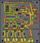
;NFT hydroponic controller to control water levels of tanks, running of NFT pump, refilling pump and air flow pump, change pumping times between daytime and nighttime, give warnings if main supply tank is low, indicat what function is active during use.
;coded for picaxe 14M2+ and use with an IBC as the NFT supply tank and connected to a rainwater tank for the reserve tank.
;change settings in start0 section to change the refilling time that is on after float switch toggles back. symbol filler_time.
;change settings in start1 level low section to change the pin values of NO or NC. Lines 61-62

; c.0  flashing red led hardware flash
; c.1  bulk tank sensor white leads input
; c.2  reserve tank sensor yellow leads input
; c.3  unused input only
; c.4  LDR input
; c.5  serial in programming
; b.0  sound
; b.1  flashing YELLOW LED hardware flash
; b.2  flashing GREEN LED sofware flash
; b.3  air pump
; b.4  refill pump
; b.5  nft pump
;symbol flash = 1    ;change for programs 2,3,4 [not used in this setup]

symbol F_Y_LED = B.2 ;flashing yellow led
symbol GRN_LED = B.1 ;green led software flash
symbol F_R_LED = c.0 ;reserve tank low warning
symbol NFT_pump = b.5
symbol AIR = b.3
symbol REFILLER = b.4
symbol DayTime = 100   ; LDR reading for day time threshold
symbol day_on = 45     ; 45 minutes
symbol day_off = 15     ; 15 minutes
symbol night_on = 5    ; 5 minutes
symbol night_off = 45     ; 45 minutes
symbol filler_time = 240 ;seconds, 4 minutes = 240 ideal for IBC tank, for smaller tank say 100L use about 30 seconds

start0:             ;check level of NFT tank and turn on filling if needed and indicate condition.
do
if pinC.2 = 0 then    ;float switch normally open, when closed trigger refilling
goto level_low
else
goto level_normal
endif
pause 100
loop
level_low:
high REFILLER         ;switch refil pump on
low GRN_LED         ;switch off green led while filling
high F_Y_LED         ; turn on flashing yellow LED to indicate filling
;********************************************************************
for b4 = 1 to filler_time     ; define 4 minutes in seconds CHANGE TO SUIT TANK SIZE
;********************************************************************
pause 1000           ; wait 1 second
next b4         ;keep from turning off the refill pump so that it does not start again too soon.
goto start0

level_normal:
low REFILLER         ;switch refil pump off
low F_Y_LED         ;switch off flashing yellow led
high GRN_LED pause 90  low GRN_LED pause 120 high GRN_LED pause 280  low GRN_LED pause 2000     ;switch on green led to show level normal

goto start0

start1:            ; check reserve tank level and warn if low
;********************************************************************
if pinC.1 =1 then reserve_low ; white leads 1 for normally closed, 0 for normally open
if pinC.1 =0 then reserve_hi    ;CHANGE TO SUIT FLOAT SWITCH
;********************************************************************
reserve_hi:
low F_R_LED         ; turn off flashing red LED reserve tank normal
goto start1

reserve_low:
high F_R_LED         ; turn on flashing red LED reserve tank low
pause 2000
     sound 0, (119,50) ; sound warning
    pause 200
    sound 0, (119,50)
    pause 200
goto start1

;--------------------------------------------------------------------------
start2:
b0 = 0           ; initialize b0 variable
main:
readadc C.4,b0     ; read LDR for night or day into variable b0
if b0 > 105 then Day
if b0 < 95 then nighttime
if b0 > 96 and b0 < 104 then waiting
goto done

Day:
low NFT_pump
for b9 = 1 to day_off
pause 60000 ; wait 60 seconds
readadc C.4,b0 ; read LDR for night or day into variable b0
if b0 < 95 then nighttime
if b0 > 96 and b0 < 104 then waiting
next b9
high NFT_pump      ; turn off the pump
for b8 = 1 to night_off
pause 60000 ; wait 60 seconds
readadc C.4,b0 ; read LDR for night or day into variable b0
if b0 < 95 then nighttime
if b0 > 96 and b0 < 104 then waiting
next b8
goto main

nighttime:
high NFT_pump
for b9 = 1 to night_on
pause 60000 ; wait 60 seconds
readadc C.4,b0 ; read LDR for night or day into variable b0
if b0 > 105 then Day
if b0 > 96 and b0 < 104 then waiting
next b9
low NFT_pump      ; turn on the pump
for b8 = 1 to night_off
pause 60000 ; wait 60 seconds
readadc C.4,b0 ; read LDR for night or day into variable b0
if b0 > 105 then Day
if b0 > 96 and b0 < 104 then waiting
next b8
waiting:
wait 6
readadc C.4,b0 ; read LDR for night or day into variable b0
if b0 > 105 then Day
if b0 < 95 then nighttime
if b0 > 96 and b0 < 104 then waiting
goto main
done:
goto start2
;---------------------------------------------------------------------------

start3:    ; AIR control
let b1 = 0 ; initialize b0 variable
readadc C.4, b1 ; read LDR for night or day into variable b0
do
if b1 > 100 then
goto air_off
else
goto air_on
endif
loop

air_on: ; subroutine for air on and off repeating
high AIR
for b10 = 1 to 15 ; define on in minutes 15
pause 60000 ; wait 60 seconds
readadc C.4, b1 ; read LDR for night or day into variable b0
if b1 > 100 then
goto air_off
endif
next b10
low AIR ; air pump is off
for b11 = 1 to 15 ; define off in minutes 15
pause 60000 ; wait 60 seconds
readadc C.4, b1 ; read LDR for night or day into variable b0
if b1 < 100 then
goto air_on
next b11
endif
goto start3

air_off:
low AIR
goto start3
") .
.