Thank's a lot for the suggestions!
Now i want even more features

But hopefully I have managed to work it out by myself.
The idea is to control the write protect pin together with the "do not remove LED"
So as i understand it, the pullup(R6) makes the picaxe read a 1 when the board is disconnected. When the board is connected the WP pullup is high and the picaxe sees a zero(pulled down through the led?), makes the pin an output high. Then current flows to the base resistor of the transistor, pulls the WP to gnd(Enable write) and at the same time current flows trough the led and it shines.
Does this make any sense at all?
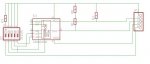
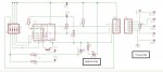
Schematic:
TP1-TP2= Wirelink to Base
TP3-TP4= Wirelink to V+
R1-R2= 4,7K I2C Pullup
R3,R5= LED resistors (value to be choosen later)
R4 = 100n capacitor
R6 = 100K pullup for PicAxe I/O pin
R7 = WP pullup (I would guess it should be around 10K?)
R8 = Base resistor for transistor BC547C (not sure what value)