Decoupling, best practise?
- Thread starter bfgstew
- Start date
I totally agree that it should be shown. Maybe they missed it out because without a decoupling capacitor it still works most of the time, or maybe they just forgot - which is why 'Have you got a decoupling capacitor fitted?' is always a question I ask, even when it's an experienced member asking the question.That's what I thought Nick, but there seems to be no mention of it in the manuals or evevn showing it the basic circuits for each chip. As this seems to be an important part of the basic operating parameter of the circuits, this info should be shown?
BeanieBots
Moderator
If only your questions could be answered with a simple yes or no.
Decoupling is a bit like sound proofing your house.
Should all windows be double glazed?
Should the doors be sound proofed as well?
Will cavaty insulation help?
You can instantly see how the answer will caveats associated with them even though the general answer would normally be yes. However, it is equally easy to see that double glazing the windows won't help if you have left the door open!
As a general rule, fit 100nF to EVERY chip as close to its power pins as possible.
I've posted several articles several times here about the how/why and where for decoupling but I've only got a few minutes spare right now so will you have to try and find them yourself. Try looking for "decoupling" or similar under my user name. It should produce a few results.
inglewoodpete
Senior Member
It doesn't seem to be particularly well documented in contempary documentation. At least I haven't noticed it.
So, being an old dog, I got out my 1978 copy of Signetics Logic TTL Data Manual. A real book made of paper")
The section called "POWER SUPPLY DECOUPLING" says...
1978 was in the early days of microprocessors and now the leaning is more to CMOS devices. However the principles were important back then and must translate into modern microcircuits to.
So, being an old dog, I got out my 1978 copy of Signetics Logic TTL Data Manual. A real book made of paper
The section called "POWER SUPPLY DECOUPLING" says...
"Power supply capacitance decoupling is required for any TTL system. Generally, 0.01uF per synchronously driven gate and at least 0.1uF for each 20 gates is required regardless of synchronisation. Counters and shift registers are especially susceptable to power and ground line noise. They should be decoupled with at least 0.1uF for each eight internal flip-flops or one capacitor for each two devices put as close as possible to the devices. Buffers and line drivers should be heavily decoupled at the driver power pins due to the current transients needed to charge and discharge the lines."
1978 was in the early days of microprocessors and now the leaning is more to CMOS devices. However the principles were important back then and must translate into modern microcircuits to.
Last edited:
inglewoodpete
Senior Member
I don't use ceramic capacitors, though. Usually MKT or monolithic types.
westaust55
Moderator
See post 13 here for sumamry of information on capacitors:
http://www.picaxeforum.co.uk/showthread.php?22009-Decoupling-caps-for-battery-powered-PICAXE-work/page2
http://www.picaxeforum.co.uk/showthread.php?22009-Decoupling-caps-for-battery-powered-PICAXE-work/page2
inglewoodpete
Senior Member
I actually don't see much of a debate. The different types of capacitors all work. Some microcontrollers work OK without them, depending on load, power source and layout. It's like insurance: they're annoying but I wouldn't be without them (decoupling capacitors).
The easiest to add are SMD capacitors to 28X2s and 40X2s and their older cousins.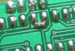
The easiest to add are SMD capacitors to 28X2s and 40X2s and their older cousins.
I have built several successful Picaxe circuit's with no decoupling at all.
I have also found decoupling to be essential in others.
It depends on the circuit and the load and the power supply.
EG:
I recently built an animated halloween prop that used three servo's, driven from four AA's.
The first tests were without any decoupling. The servo's jitterd and twitched and the LEDs flickered.
Then I put a 220nF cap across the Picaxe and a 470uF cap across each servo. Then it worked perfectly. Rock solid.
Decoupling ICs from the supply has been standard practice forever. Why Rev Ed has ignored this in their manuals is a mystery. Not only does decoupling reduce power supply noise coming from the supply, it also helps to prevent noise generated by the IC from getting on the supply rail. There is no good excuse for not using a decoupling capacitor with a Micro.
Most IC Mfgs specify a ceramic capacitor between .01uf to .1uf as close to the IC's supply pin as possible. What is often overlooked is that the ground side of the cap should connect to a relatively large area ground plane through a via or a short trace to minimize inductance.
Most IC Mfgs specify a ceramic capacitor between .01uf to .1uf as close to the IC's supply pin as possible. What is often overlooked is that the ground side of the cap should connect to a relatively large area ground plane through a via or a short trace to minimize inductance.
jedynakiewicz
Senior Member
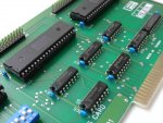
Have a look at what is done commercially... Fig.1 illustrates a vintage 8255 TTL input/output board from the old IBM PC era - though very relevent to the type of DIL / TTL circuitry most PICAXE users are involved with. - Every integrated circuit on the board is decoupled with 100nF right up against its power input pins.
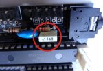
With regard to the type of decoupling capacitor see Fig.2. PICAXE boards appear to be supplied with 100nF polyester capacitors for decoupling.
Observing this, I usually have a 50+ stock of 100nF 63v 5mm Polyester box capacitors in my parts drawers (Part no. 10-3260 from Rapidonline.com) and I follow very much the advice of Inglewoodpete and put one on each and every power supply next to an active i.c.
PICAXE manual 3 advises using a 220nF polyester capacitor across the brushes of small electric motors. (Part no. 10-3264 from Rapidonline.com)
I have checked out the effect of the 220nF polyester capacitors with an oscilloscope on the the small motors that I commonly use and the effect is dramatic. Even so, after getting my fingers burnt with various forms of interference on the line from motors or actuators I now always design with two separate power supplies; one for the PICAXE and associated chips and a second one, usually from a secondary winding on the power transformer, for any motors or actuators. This seems to give 100% reliability.
I absolutely agree that the PICAXE technical reference manuals need a decent paragraph or two on the subject of decoupling. It is one of the most mentioned topics on this board and yet it is ignored in the PICAXE manuals. Obviously if only one PICAXE chip is being used in a simple battery-driven circuit and the inputs are switches, the outputs LEDs, then it is likely that the thing will work without decoupling. Add one interface chip to the story and then decoupling is a must.
Attachments
-
 115.5 KB Views: 27
 -
 79.5 KB Views: 26
Very good telling point from Goeytex. Also the reason that ceramic plate or stacked constructions are used and not rolled up constructions which will exhibit minor inductances. The surface mount capacitor is probably as good as you can get when it comes to minimising stray inductance.What is often overlooked is that the ground side of the cap should connect to a relatively large area ground plane through a via or a short trace to minimize inductance.
@bfgstew, I think that at each transistor or FET is perhaps taking the paradigm to extremes. Most IC's are a collection of many transistors potentially generating a lot of switching noise. A case for moderation, in all things I suspect!