Dc motor speed control

arg733

Senior Member
Hi.
Thanks for accepting me on the forum.
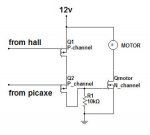
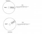
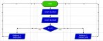
I have a problem and someone on another forum told me that a picaxe would solve it and redirected me here. I have a dc motor of my own making which I need to run under constant rpm under highly variable loads. My motors slows down when I give it bursts of power instead of continuous supply so I thought that I needed something to read the RPMs from a hall sensor, and if the RPMs go above the specified value, increase the frequency and decrease the duty cycle of the busts. If the RPMs drop below the specified value it should decrease the frequency and increase the duty cycle. I googled everything I could think of from but did not found anything that suits my needs. So I asked for help on electronics point forum and someone told me to get a picaxe (as I have no pic programmer) and thankfully provided a schematic. As the schematic suggested I got a 08m2 but now am in the difficult position to program the picaxe. I have never done any programming of any sort as i am only 16. I managed to do something in the logicator in flowchart format (attached bellow) but as you can see it only jumps from one state to the other instead of incrementally increase and decrease the frequency and duty cycle for example when the RPMs jump from 5000 (threshold value) to 5200 it should give 15khz 30% when the RPMS go 5500 it should give 20khz 20% and so on... My idea is to supply steady frequency that will correspond to 5000 RPMs from a function generator to C5 and the hall readings to C3 and get the output from C2…
Sorry if all that sound confusing but my English isn’t perfect.
Thank you for your time and tell me if you need more information.
 

Attachments

SAborn

Senior Member
Your English is perfect to me.

The function you would be best to use to control power to the motor is "PWMout" have a read on the instruction in manual 2.

You have not said what voltage and what current you motor requires, we need to know.

Do you have a download cable to connect the computer to the picaxe board. (usb to serial adapter, or serial cable if your computer is old enough to still have a Com port)

Its a tough project to start out learning to use a picaxe, and you will need to break each section into its own, and get each section working before you try to string it all together in one big program.
 

arg733

Senior Member
Thanks the motor is controlled by another driving circuit I just need logic level output from the picaxe I will then amplify it. The pwmout command was the first I looked at when I first opened the pdf but I could not understand basic and I tried the flowchart. I made some progress but my problem is ho to make it increase and decrease the frequency incrementally. Believe me I would not start my first programming attempt with so difficult project by I need it very much, I have all the required hardware the programming is the issue for me.
Thank you.
 
Last edited:

BeanieBots

Moderator
As suggested by SAborn, this is not an easy first program.
Before attempting to write any code, the first thing to do is to actaully solve the problem.
For example, how rapidly will your load change? The answer will help determine if you should use 'count' or 'pulsin' to measure speed.
Why do you want to change the frequency of the PWM? This is not a common method of speed control but maybe have specific reason.
It is far more common to run at a fixed frequency and change the duty cycle.
What frequency can your drive electronics run at? What frequency will your motor be happy with?
How accurately do you need to maintain the speed?

I strongly suggest that you do this by programming in BASIC rather than using Logicator.
There are far more people here that will able to help with BASIC and you will probably need to write lines of BASIC within Logicator anyway.
 

arg733

Senior Member
Hi my load can change from 10% to 50% in a matter of seconds and i saw that frequency is a more effective control method for my motor as i can play with frequency from 2khz to 50khz my driving can handle just about any frequency up to 100khz with no problem. I am basically a quick learner and i figured the flowchart quickly enough but when I look at basic and any other programming language it has the same effect on me : my head blows up. Here is my code (automatically translated by the logicator from my flowsheet, in basic if that helps)

So when i simulate the program jumps from 5khz to 20khz how do i tell it increase the frequency by 20hz let's say at each 1rpm of ofset.

Code:
'BASIC converted from Logicator for PICAXE flowsheet:
'C:\Documents and Settings\DIMITRIS\My Documents\Flowsheet1.plf
'Converted on 2/9/2012 at 22:15:01

;Symbols 
{
symbol varA = b0
symbol varB = b1
symbol varC = b2
symbol varD = b3
symbol varE = b4
symbol varF = b5
symbol varG = b6
symbol varH = b7
symbol varI = b14
symbol varJ = b15
symbol varK = b16
symbol varL = b17
symbol varM = b18
symbol varN = b19
symbol varO = b20
symbol varP = b21
symbol varQ = b22
symbol varR = b23
symbol varS = b24
symbol varT = b25
symbol timer = time
}


let dirsC = %00000001


main:
label_1:
		count 5,100,varA
		count 3,100,varB
		if varA > varB then label_6	'Compare command
		pwmout 2 , 199 , 640
		goto label_1

label_6:	pwmout 2 , 49 , 40
		goto label_1
 

BeanieBots

Moderator
The PICAXE PWMout command is more suited to variable duty than frequency so it will make much easier to vary the duty.
The PWMout command should only be executed once to setup the output. After that, use the PWMduty command to vary the duty cycle.

I'm not sure why you counting on two inputs. Is one the desired speed and the other the actual speed?

Controlling motor speed is the infamous PID which scares most people but as long as your system response is reasonably slow you might get away with simply adding or subtracting an amount from the value for duty.

Try something like this:

Code:
Symbol Speed = w0
Symbol Demand = w1

PWMout 2,199,1 'start pwm pulses
Main:
  count 5,100,Speed                             'measure the speed
  count 3,100,Demand                          'measure the demand

   If Demand > Speed then
        Duty = Duty + 1 MAX 800          'increase up to maximum value  
        else
        Duty = Duty MIN 1 -1                  'decrease down to minimum
   endif

  pwmduty 2,Duty
  Pause 250                                        'experiment with this value
Goto main
 

arg733

Senior Member
Thanks as you see the C5 is the desired speed and C3 is the actual speed

when i run the simulation it says "Error: Unknown symbol - Duty"
what should i change?
 

arg733

Senior Member
Ok thanks problem with the simulator seems to be solved except that i dont see if it really stores the counted pulses.
should i change w0 w1 w2 with? b0 b1 b2

i tried with b but the result is the same.
 

BeanieBots

Moderator
The simulator needs to be 'told' the values for count. (don't use it much myself so can't advise)
You MUST use word variables (due to values used) and NOT byte variables so no, do NOT change w's to b's.
b's are 0-255, w's are 0-65535. PWMout duty is 0 - 800 so it MUST use a word variable.
 

arg733

Senior Member
ok so if i actually program the picaxe it will work right?
i use the "Picaxe programming editor" to simulate.
 

BeanieBots

Moderator
It MIGHT work.
Controlling motor speed is far more complex than simply increasing or decreasing pwm duty depending on if speed is too high or too low.
Look up "PID" with google.
In some cases, you MIGHT get away with something simple but you WILL need to do some experimenting with the pause value.
(that's the iteration value in a PID loop. The code I posted is only for the "I" term)
As I mentione in post #4, YOU need to solve the control problem. Then we can help with the code.
Try it and let us know how it behaves.
I would expect you will need the "P" term as well for stable control but you MIGHT get away without it. It all depends on the dynamics of your whole system.
 

arg733

Senior Member
wow that was fast thanks...
i know it will work. i played with my function generator to try to keep the rpms constant and it worked pretty well i thought to use a mechanical governor to pull the pot if i didn't find a solution with electronics, but its difficult to find a governor for 5000+ rpms and it's not as rapid and precise as an electronic way of control
 

BeanieBots

Moderator
Don't forget that YOU are very good at PID control. YOU will even be employing feedforward when YOU control the function generator. I bet you even adjusted it slower if you noticed a smaller change. These are very basic things we do without thinking. The poor old PICAXE can't think for itself. It can only do what you ask it to do.
Anyway, TRY IT.
If you are not happy with how it perfroms, describe in detail how it behaves and we can probably make it better without getting too complex.
 

arg733

Senior Member
Thanks i will try it and post the results.
I didn't really get what the pdf means that if the picaxe is left without power the program will be lost?? does this mean that i must keep it powered by batteries and/or supercaps?
 
Last edited:

JimPerry

Senior Member
No. Program stays in chip without power - puzzled me for a while! :confused: It's not actually stated in the documentation clearly :rolleyes:
 

arg733

Senior Member
manual 1 states:
"To perform a hard reset using the power supply (all sizes):
1) Disconnect the power supply.
2) Wait until all power supply decoupling capacitors have discharged (can take
up to 30 seconds or more depending on circuit design).
3) Click the PICAXE>Program menu to start a download.
4) Wait until the progress-bar appears on screen.
5) Reconnect the power supply"
what does this mean?
 

RobertN

Member
To start with a simple program, do a period measurement of 1 pulse per revolution. Compare that value with the target interval that represents the desired RPM. If the period is too long, turn on the motor drive 100%. If the period is too short, turn off the motor drive to 0%. This will give you a simple free running PWM of the motor drive. Some additional tweaking may give you the results you are looking for.
 

SAborn

Senior Member
manual 1 states:
"To perform a hard reset using the power supply (all sizes):
1) Disconnect the power supply.
2) Wait until all power supply decoupling capacitors have discharged (can take
up to 30 seconds or more depending on circuit design).
3) Click the PICAXE>Program menu to start a download.
4) Wait until the progress-bar appears on screen.
5) Reconnect the power supply"
what does this mean?
That just means if a program loaded to the chip locks you out of downloading a new program to the chip, then a hard reset is required to get the chip to except the new program.

All very simple and not required to be used that often, but if the download fails then a hard reset is used.
 

arg733

Senior Member
Ok thanks the manual confused me a bit, but now i get it. Am i correct to assume that if i change the "pause 250" i will change the "refresh rate"?
 

arg733

Senior Member
Robert i am not quite sure what you mean but if i understand you correctly you suggest that i need to take some readings from the motor that can only be done using an oscilloscope which i don't have :)
 

BeanieBots

Moderator
Robert is suggesting that you should use pulse width rather than pulse count to measure the motor speed which I agree with.
However, I do not agree with his suggested control method of on/off.
As I've mentioned before, writing lines of code to do what you want is the easy part. The hard part is knowing what you need the code to do. Without test equipment such as a 'scope you (and we) can only guess.
 

arg733

Senior Member
To start with a simple program, do a period measurement of 1 pulse per revolution. Compare that value with the target interval that represents the desired RPM. If the period is too long, turn on the motor drive 100%. If the period is too short, turn off the motor drive to 0%. This will give you a simple free running PWM of the motor drive. Some additional tweaking may give you the results you are looking for.
Just to clarify the motor is brushless it operates using a hall sensor which is very similar to brushed operation with the only difference that it has a permanent magnet rotor. So it doesn't need pwm to operate. It was my observation that when i interfere with the hall's signal and make it pulsed instead of continuous the magnetic field of the coil drops dramatically so the speed of the rotor drops. Hope that helps to understand how my motor works (sorry for the lack of information)
I have a schematic attached to give you an idea of how i will utilize the frequency from the picaxe.
 

Attachments

Last edited:

arg733

Senior Member
I dont need anything complex i need the picaxe to count the pulses just as my rpm counter with the difference that the picaxe will be counting in hz and not rpms.
To slow the motor i just needs to give it some 10.000 - 20.000 hz and PREFERABLY but not necessarily duty cycle from 50 to 20% and to accelerate it i must give 2.000-5.000hz and duty cycle from 50 to 80%. As you see it's very easy to control my motor :) it's the code that i cant figure out on my own yet.
 
Last edited:

arg733

Senior Member
So i just connect the serial cable (when i have the pcb ready) paste the code and hit the program button?
 

BeanieBots

Moderator
As you see it's very easy to control my motor :)
Umm... no... I can't see! I have zero concept of how you are controlling that motor with that circuit!
I have no idea about how to go about 'adjusting' the hall feedback of a brushless motor with another (non-synchronised) PWM signal to control speed so I'll bow out of this gracefully and leave it to others who may be able to hlep.
 

arg733

Senior Member
Umm... no... I can't see! I have zero concept of how you are controlling that motor with that circuit!
I have no idea about how to go about 'adjusting' the hall feedback of a brushless motor with another (non-synchronised) PWM signal to control speed so I'll bow out of this gracefully and leave it to others who may be able to hlep.
don't confuse the pwm signal with the hall sensor signal the motor doesn't need the pwm to operate. i will try to explain it as best as i can...

I have a small magnet attached to the shaft which activates the hall sensor. When the hall sensor activates it sends a signal to the N-channel which allows the current to flow through the coil of the motor. So lets imagine that the small magnet is in front of the hall sensor, this means that the hall is now active and sending a signal to the gate of the upper p-channel mosfet (lets call it Q1) and the other p-channel that takes signal from the picaxe (Q2) does not exists. So the motor runs on its own hall sensor no need for pwm. OK lets pause at the moment that the magnet passes in front of the hall, lets put now the second p channel and apply a frequency. What will happen? Instead of a steady current flow to the motor when the hall activates we get a pulsed current so the coil doesn't have enough time to draw all the amps it's supposed to. As we increase the frequency and decrease the duty cycle of the pulses the coil draws even fewer apms Its just like dimming a led with frequency and duty cycle.
 
Last edited:

arg733

Senior Member
nope my motor isn't stepper it can run on its own just like a brushed steppers can't run on their own my motor has the same method of operation with a brushed dc motor.
There is no such controller that what i need that's why i need to make one...
When the hall applies power to the motor the coil kicks the magnet forcing it to spin. If it remains energized the rotor will be kicked back the hall must be turned off before that happens. Brushed motors use the same method of operation the only difference is that the brushes do the switching and not the hall.
 

arg733

Senior Member
it's my own motor i made it my self so here how the hall works. It supplies power when the rotor is in position A and cuts power before it reaches position B (if power remains on the rotor will get a kick forcing it to spin in the opposite direction and will be forced in a loop going back and forth from position A to B that's why i need to cut power before it reaches Position B.
The frequency will have the same effect on it as a dimmer has on an AC motor or a lamp.
This is a very rough representation of the motor
 

Attachments

arg733

Senior Member
nope just the hall sensor remains open for 25 degrees after position A then after those 25 degrees it is switched off as the magnet that activates it is no longer in range, so when it's switched off well before it reaches position B
 

SAborn

Senior Member
So would it be fair to say, that when the hall sensor is "High" power is supplied to the coil, and when the hall sensor goes "Low" it cuts the power to the coil, then the process repeats when the next magnet take the hall sensor High again.

This would mean you are switching the mosfet on and off with a slight pause in between cycles to control the motor speed, or in otherwords controlling the motor with a frequency.
 

arg733

Senior Member
So would it be fair to say, that when the hall sensor is "High" power is supplied to the coil, and when the hall sensor goes "Low" it cuts the power to the coil, then the process repeats when the next magnet take the hall sensor High again.

This would mean you are switching the mosfet on and off with a slight pause in between cycles to control the motor speed, or in otherwords controlling the motor with a frequency.
Yeah that is correct, when i didn't knew about hall sensors, i was trying to control it by frequency, but this was very difficult as a slight over frequency was forcing it to stop and turn backwards, after that i tried copper commutator or "collector" with brushes (just as the distributor in an internal combustion engine) giving a pulse to the gate of the mosfet, and only after all that i found out about the hall sensors. This worked fine in non variable load conditions but i needed variable loads and started searching... that's where the picaxe comes in...
 
Last edited:

hippy

Ex-Staff (retired)
What we seem to have is a motor which is turned by dragging its magnet towards an energised coil and then turning that coil off as it passes, turning it on to pull the next through and so on. That seems pretty standard and is the principle of a stepper and most other motors.

Where this seems to vary from a normal stepper which uses a PWM to determine how often and for how long the coil will be fully energised to pull the magnet through, the energising is automatically handled by a hall effect switch, and the PWM is instead being used to control the power of the energised coil.

That at least is my understanding of it but I could be wrong. A block diagram of everything would probably help clarify exactly how things are.
 

arg733

Senior Member
What we seem to have is a motor which is turned by dragging its magnet towards an energised coil and then turning that coil off as it passes, turning it on to pull the next through and so on. That seems pretty standard and is the principle of a stepper and most other motors.

Where this seems to vary from a normal stepper which uses a PWM to determine how often and for how long the coil will be fully energised to pull the magnet through, the energising is automatically handled by a hall effect switch, and the PWM is instead being used to control the power of the energised coil.

That at least is my understanding of it but I could be wrong. A block diagram of everything would probably help clarify exactly how things are.

yes that was a perfect description hippy that is exactly the case only i couldn't give that explanation because am generally not good at giving explanations and examples and my English is not that perfect. I want to use the frequency as someone else would use the voltage to control the power of the motor (weird heh?) but i found that controlling the voltage is far more difficult than controlling the frequency.

Edit: slight change there hippy, i use repulsion and not attraction (this is basically the same way of operation, the only thing that changes is the position of the hall sensor's magnet) the sketch i draw is for repulsion operation (it may confuse someone if he sees the sketch and thinks that it works with attraction).
I don't know why but i prefer repulsion.
 
Last edited:

BeanieBots

Moderator
OK, a little clearer now what you trying to do. (though it sounds very much like a BLDC motor).
In which case, I would use the hall sensor to gate the PICAXE PWMout and use the code I suggested.
Though you will need to ensure that your PWM frequency is significantly higher than the hall sensor rate or you will get beat frequencies that will put all manner of nasties into the mechanics. Ideally they would be synchronised which might be possible with PICAXE hardware interrupts.
 

SAborn

Senior Member
Is this the sort of circuit you want to use in the drawing below.

How i understand this to work is the picaxe supplies a PWM of 10Khz frequency to Q2 for control of the current to the motor, Q1 switches the motor coil on/off using the signal from the hall sensor, the hall sensor is also monitored by the picaxe and if the frequency of the hall sensor changes (motor rpm changes) then the duty of the PWM is adjusted to alter the current to the motor, to maintain a constant motor RPM under load.


Basic block diagram
Motor control.JPG
 
Top