Datalogger AXE110, possible to log 4 analouge channels ?

bonaur

New Member
Hi All.

1.
I have purchased the AXE110 so i can log 4 analouge channels, but i seems that input 7 is dedicated to the temperature sensor.
Can i just rename the basic code from 'readtemp' to 'readadc' ?

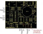
2. How do I spot the 2 resistors I will need to cut off, one 10kOhm pull-down for the 'LDR-input0' and one 4,7kOhm pull-up for the temperature sensor ? (Input 7)
As I will not need pull-up/down for my data-logging mission.

Best regards, Bo Andersen.
 

westaust55

Moderator
Datalogger AXE110, possible to log 4 analogue channels ?

The two mentioned resistors to remove are identified in the attached diagram

However, the 18X (as used on the AXE110 data-logger) only has 3 analogue inputs available. ADC0, ADC1 and ADC2
Have a look at the layout in Manual 1 page 6
 

Attachments

Last edited:

bonaur

New Member
The two mentioned resistors to remove are identified in the attached diagram

However, the 18X (as used on teh AXE110 datalogger) only has 3 analogue inputs available. ADC0, ADC1 and ADC2
Have a look at the layout in Manual 1 page 6
Hmm crap.
Thanks for the image showing the 2 resistors.

Then it must be possible to use a 2.nd PICAXE (I have one in spare) and make a SERIN/SEROUT routine in the MAIN: program of the 18X-datalogger. Using output6 and input7.
Something like:

main: 'Serin/serout routine for 18x datalogger'
high 3 ' flash LED
serout 6,N2400,("GO1") 'Send GO1 signal to 2.nd PIC'
serin 7,N2400,b3 'Wait for 2.nd PIC to send data and store it in b3'
readadc 0,data0 'Regular analouge reading from the datalogger-mission'
readadc 1,data1 'Regular analouge reading from the datalogger-mission'
readadc 2,data2 'Regular analouge reading from the datalogger-mission'
low 3 ' end of flash LED


Program for 2.nd PIC
main: 'Serin/serout rouine for 2.nd PIC'
serin 1,N2400,("GO1") 'Wait for GO1 signal from 18x datalogger'
readadc 0,b1 'read analouge value on pin 0 into b1'
serout 1,N2400,b1 'transmit the value/byte to 18x datalogger'
goto main

Will this work ?
Best regards, Bo Andersen.

PS: This is getting way more complicated than first anticipated, but hey it's still fun.
 

moxhamj

New Member
If your program is simple maybe have a look at some of the other picaxes. It is a bit of a secret that the 14M actually has 5 analog inputs, and it is cheaper than an 18X. The pre-built boards are great for building that exact project, but once you have mastered that it is soon time to build your own boards.
 

kranenborg

Senior Member
I do not know if output 7 and output 6 are available directly without any pullups etc, but if so, you can actually reconfigure them as ADC inputs, see the following link: http://www.picaxeforum.co.uk/showthread.php?t=9289 , giving a total of 5 ADC inputs (indeed standard 3 are availabe, but some poking "under the hood" gives two extra)

EDIT: Just checked the AXE110 datasheet, should be possible on both OUT6 (via CT9) and OUT7 (via CT2) without any modifications ...
Let me know if this suits you, I can help if needed.

IMPORTANT: Connect the new ADC input (out6/7) to the sensor vi a 1K resistor in series; at startup it is an output and this may generate large currents.

Regards,
Jurjen
 
Last edited:

hippy

Ex-Staff (retired)
However, the 18X (as used on teh AXE110 datalogger) only has 3 analogue inputs available. ADC0, ADC1 and ADC2
Have a look at the layout in Manual 1 page 6
Officially the 18X has only three ADC inputs, but as the output pins can be made inputs that gives access to an additional two ADC inputs if their being outputs at reset can be worked round.

How the datalogger would need to be modified for such use I have no idea. It would probably be easier to connect passive components ( LDR, pots etc ) to these 'inputs' rather than active components.
 

bonaur

New Member
I do not know if output 7 and output 6 are available directly without any pullups etc, but if so, you can actually reconfigure them as ADC inputs, see the following link: http://www.picaxeforum.co.uk/showthread.php?t=9289 , giving a total of 5 ADC inputs (indeed standard 3 are availabe, but some poking "under the hood" gives two extra)

EDIT: Just checked the AXE110 datasheet, should be possible on both OUT6 (via CT9) and OUT7 (via CT2) without any modifications ...
Let me know if this suits you, I can help if needed.

IMPORTANT: Connect the new ADC input (out6/7) to the sensor vi a 1K resistor in series; at startup it is an output and this may generate large currents.

Regards,
Jurjen
Looks promising, thank you.
Hmm it seems the Datalogger AXE110 uses OUT7 for the datalink routine ?
But anyways just OUT6 needs to be conveted to an input ADC pin.

The code that converts the output to input, only needs to be executed once in every program, right ?
And afterwards PIN12 (was OUT6) can now be read by the 'readadc 6,xx' command, right ?

The code for converting only OUT6 (Pin 12) how does that look ?
I have copied and altered the code from above link, will you please have a look at it ?

Code:
REM Example program
REM Shows how OUT6 on a PICAXE 18X can be converted into ADC inputs
REM thus increasing the max number of 10-bits ADC inputs on this device to 4

SYMBOL IO_Direction = b0
SYMBOL Shadow_TRISB = $AE
SYMBOL ANSEL = $9B
SYMBOL ADCON0 = $1F
SYMBOL ADCON1 = $9F
SYMBOL ADRESH = $1E
SYMBOL ADRESL = $9E


REM First convert OUT6 (and leave the state of the others as they were)
REM using hippy's "shadow" TRISB register

PEEK Shadow_TRISB,IO_Direction
LET IO_Direction = IO_Direction OR %10000000 '(CHANGED BIT6 to "0" ASSUMING BIT6 CONTROLS OUT6 ?)'
POKE Shadow_TRISB,IO_Direction												

DO
	
	REM Do an ADC read on pin 12 (was OUT6, will be AN5 now).
	REM First enable the ADC functionality
	POKE ANSEL,%01100000								REM Set ANSEL register: Analogue inputs enabled on AN5 (RB6), AN6 (RB7)
	POKE ADCON1,%10000000								REM Set ADCON1 register (
	POKE ADCON0,%11101001								REM Set ADCON0 register (AN6 input); Enable the AD module
	REM Now do the actual ADC conversion 
	POKE ADCON0,%11101101								REM Start actual ADC conversion
	REM Get 10-bit result in w0
	PEEK ADRESH,b1											REM Read upper 2 bits of AD convertion result.
	PEEK ADRESL,b0											REM Read lower 8 bits of AD convertion result.
	POKE ADCON0,%11101000								REM Disable AD module

	POKE ADCON1,%00000000								REM Restore ADCON1 settings for proper READADC functioning
	
'DELETED OUT7 ADCON ROUTINE'
	
	REM Show 10-bit result for the two new ADC channels
	SERTXD("ADC pin 12: ", #w0, "  ADC pin 13: ",#w1,13,10)
	
	PAUSE 1000

Main: 
'The rest of the datalogger mission, with modifications regarding readtemp -> readadc'
How does it look ?

Best regards, Bo Andersen.
 

kranenborg

Senior Member
Hi Bo,

Indeed the output to input conversion needs only be done once, at the begin of the program. Use a 1K resistor to tie the pin to your sensor.

You can not use a READADC instruction for this pin ;you actually simulate it with the program code.

Your code adaptation is almost right i think, best put the ADC part (just after DO, until (and including!) POKE ADCON1,%00000000) in a separate subroutine; after callign it the 10-bit result will be available in w0. In this way the subroutine actually simulates a READADC10 out6, w0 instruction! You need to call the subroutine everytime you want to read the input. You could if needed speed up the execution by temporarily increasing the clock frequency to 8 MHz.

You should remove the DO command (it was in my code for implementing the loop for continuously reading and then printing the ADC results)

Success!
/Jurjen
 
Last edited:

boriz

Senior Member
In theory, you could ‘multiplex’ a single ADC to respond to multiple sensors thus:


With OP1 hi and OP2 low, you are reading the light sensor. With OP1 low and OP2 hi, you are reading the temperature sensor.
 

bonaur

New Member
Hi Bo,
Your code adaptation is almost right i think, best put the ADC part (just after DO, until (and including!) POKE ADCON1,%00000000) in a separate subroutine; after callign it the 10-bit result will be available in w0. In this way the subroutine actually simulates a READADC10 out6, w0 instruction! You need to call the subroutine everytime you want to read the input. You could if needed speed up the execution by temporarily increasing the clock frequency to 8 MHz.
Success!
/Jurjen
Hi Jurjen.
Thank you for your response.

Ok, I think I got it now, I will make a sub routine and call it everytime when needed.
However I will 'only' need to do an 8bit conversion, can this be done directly or must I recalculate the result ?:
Code:
...some code...
REM Get 10-bit result in w0
PEEK ADRESH,b1								REM Read upper 2 bits of AD convertion result.
PEEK ADRESL,b0								REM Read lower 8 bits of AD convertion result.
POKE ADCON0,%11101000

REM convert w0 from 10bit to 8bit resolution
let w0 = w0*256/1024
REM copy the least significant byte (b0) from w0 into b3
let b0 = b3
...rest of the code...
BWT the code adaptation for converting only OUT6 is that correct ?
Code:
LET IO_Direction = IO_Direction OR %10000000 '(changed bit6 to "0" assuming bi6 controls out6)'
Thank you for your time.
Best regards, Bo Andersen.
 
Top