Data Logger using multiple 08Ms

BjBlaster

New Member
Hi Guys,

I'm building a data logger using 08ms for temp sensing and solar panel / battery monitoring. I was wondering if anyone has managed to make a rs232 serial "bus" than can interconnect to multiple PICAXEs (08m) to share the one PC com port. I have each of the 5 x 08m's doing a job like voltage measurement, temp etc, but can only feed one at a time into the rs232. I also wanted to expand it later. I've written some software in linux to read my Pics and do the relevant software maths for the temp sensors and then upload it to a ftp server.

I 'm not to sure how to get the handshaking to work so each PIC gets to say it's output to the "bus" without conflicting with another PICs message.

I tried using a third wire using pins 3 and 4 as a stop/go data control but there must be an easier way?!

Thanks

Bj
 

womai

Senior Member
For transmission from the PC to the Picaxes, just hook all the receiver inputs together. The PC then uses qualifier strings before the actual data to tell the Picaxes which one it wants to talk to (e.g. "01" for the first Picaxe, "02" for the second, and so on). The Picaxe code is then along the lines of

serin 1, N9600, ("03"), b0 ' receive code for Picaxe 03

For transmission from the Picaxes to the PC, one option is to "diode-OR" the transmit outputs of all Picaxes, i.e. insert diodes pointing from the Picaxes to the PC, into a shunt resistor (maybe 220 Ohm or so) to ground. That way if any single Picaxe drives "high" on its serial output, the PC will see high, otherwise it will see low. So as long as only a single Picaxe is transmitting at any given time, data will get to the PC just fine, and all the other outputs are effectively removed from the line because of the diodes.

The easiest way to avoid collisions is to implement a strict master-slave scheme: The Picaxe (slave) only answers after the PC (the master) has asked for data. That way the PC can query one Picaxe after another, each time waiting until it receives the response before querying the next Picaxe. This assures that there are never two Picaxes transmitting at the same time.

Wolfgang
 
Last edited:

BjBlaster

New Member
Perfect! I'll modify the software to ask each PIC for some data - That's a much better idea... Will report back how it all comes together :)

Thanks for your help Wolfgang!

Cheers

Bj
 

hippy

Ex-Staff (retired)
That diode-mixing works well and is perfectly suited to "PC asks, addressed PICAXE responds" which is very simple to implement.

In systems where any number of PICAXE's may want to 'randomly' communicate with the PC without being prompted ( door bell push detectors say ), another PICAXE can be added as an arbitrator. Each PICAXE sets an output asking for access to the PC, the arbitrator scans those signal lines looking for a request and grants a single PICAXE permission so it can go ahead and send. When the PICAXE finishes sending, it clears its request line, and the arbitrator will go back to scanning and give another PICAXE access. Each PICAXE has to tell the PC who it is so it knows where the data came from.

The "request then respond" and this arbitrary communications mechanism can, with a little more effort, be integrated together allowing quite advanced PC and PICAXE control networks to be formed.
 

manie

Senior Member
Bj: Thanks for the question, its helped me already for something in the back of my mind.

For the responders: Thats why we noobs ask these questions, never too old to learn, and SAD is the day when you DO NOT learn something NEW !
Manie
 

BjBlaster

New Member
Ok,

I had a crack at it last night and managed to get it working! A good tip for young players (ie me!) is make sure you tie the programming leg2 to ground or it gets all corrupted.

I used pin4 for the serin and it works fine. The other thing I can't find any examples of are the serin timeout format? I added this feature to my roof fan controller, but the whole code waits until is sees some serial in action before turing on the fan (or off)

Code:
sendstuff:
		serin 4,n2400,("roof") 'send id to this pic
		pause 100
		serout 0,n2400,(b0)
		pause 100
		return
Thanks
 

lbenson

Senior Member
Sadly, no timeout feature for serin on the "M" series chips. A big and longstanding problem. There is a two-chip solution--one 08M sits in serin forever. When it gets a message, it signals the controller 08M by pulling a line high. When the controller sees the line high in the course of its normal looping, it pulls another line high and goes into serin. When the first sees that line go high, it serouts its data and pulls its line low. If it doesn't see the second line go low, it sends again. When the controller gets the data it pulls its line low and returns to looping. Then the first 08M re-enters serin.

Not so pretty, but it's what we have. Other two-chip options are available. Search for "serin hang".
 

BjBlaster

New Member
No wonder it wouldn't work! Thanks for the info on the 2 chip idea, that could come in handy later - but for this I just get the PC to poll it every 2 seconds that works for just a fan :)

Thanks again.

Bj
 

hippy

Ex-Staff (retired)
Getting PICAXE/PC networks just right can be a bit of a challenge. As long as it's wait for the PC to send, do something then respond, or wake-up the PC then wait for a command, and similar, things should be straight forward.

When it's 'wait for PC or do something else' it can rapidly get quite complicated. You have to consider what happens if something the PC sends gets missed, such as when it sends just after the PICAXE has decided the PC isn't sending. This can lead to dead-lock, the PC waiting for a response while the PICAXE which would respond is waiting to hear from the PC.
 

kranenborg

Senior Member
Hello,

You may have some interest in investigating my "SerialPower" network concept ( http://www.picaxeforum.co.uk/showthread.php?t=7694 ), as it allows any number of picaxes (including 08m) to communicate with each other (including slave-to-slave) and bus clashes are avoided automatically. The protocol actually appears to resemble a simplified LIN-bus protocol (although not intentionally), using separate timeslots for each process ID to guarantee communication without conflicts.

In your application it would probably mean that the master node (or maybe a slave node) would connect to the PC. Note that in its most powerful form (some of) the picaxes nodes may be powered from the bus itself, since it is essentially a true two-wire data+power bus. A standard three-wire bus is also possible. No handshaking lines are needed since it uses hippy's "serial interrupts" as the fundamental signalling concept.

This reminds me also that I have to upgrade the SerialPower website ... ;o)

Regards,
Jurjen
 

BjBlaster

New Member
I did it the easy way :) I have a cat5e network around my house, so I just set each node up on a "BUS" that is the cat 5 cable. The bl/brn pairs are power, and the grn/org pairs are for data. I made up a hub that can be expanded to patch the ports to. It is nothing more than paralleled sockets with a 12V supply tied into the power pairs. I'll post it up on my site when I finish documenting it.
www.bjblaster.com

Cheers

Bj
 

BjBlaster

New Member
O8M vs 20M

So I managed to get my logger working quite well, but I thought I'd up the anti and add a few more inputs using a 20M instead of a 08m for my new gir d fed solar rig. What am I doing wrong? I've been through the docs and can't see why this won't work on a 20M? It runs fine on a 08m!

Code:
start:
let b0=0
serin 4,n2400,b3,b4
'serout 0,N2400,(b3,b4)
pause 100
if b3="1" and b4="1" then goto readsolar
if b3="1" and b4="2" then goto readbatt
goto  start

readsolar:
pause 100
readadc10 1,w0 ‘ read value into w0
serout 0,N2400,("sv:",#w0)
'serout 0,N2400,("           ")
'second reader
goto start

readbatt:
pause 100
readadc10 2,w1 ‘ read value into w1
serout 0,N2400,("bv:",#w1)
'serout 0,N2400,("           ")
pause 100
goto start
Wired the same as the 08m (pin wise) all I get is either junk replies from the serout or 4949 instead of a "11"?

Has anyone else had trouble "expanding" from a 08m to a 20m? I guess there is some secret stuff going on like "you can't use such and such pin with that mode enabled? story?

Thanks for any help guys.

Bj
 

eclectic

Moderator
Bj.
Possibilities, until you get an expert answer.

08M programs should port to 20M

Manual 1, pages 25 and 27.
Make sure that the Pin- connections are correct.

Then from manual 2 page 127
Code:
Data are variables/constants (0-255) which provide the data to be output.
In other words, you can only serout bytes (0 – 255)

Try this for instance
Code:
; Instead of

serout 0,N2400,("sv:",#w0)

;Use


serout 0,N2400,("sv:",b0,b1)

;Then read in 
serin (pinnumber), N2400,(“sv:”), b0,b1

sertxd (#w0)
e
 

Attachments

hippy

Ex-Staff (retired)
Wired the same as the 08m (pin wise) all I get is either junk replies from the serout or 4949 instead of a "11"?
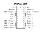
Something to do with ADC1 and ADC2 being on different pins on the 20M to where they are on the 08M perhaps ?

Take a look at page 8 of PICAXE Manual 1 for pinouts.
 

BjBlaster

New Member
Well what doesn't make sense is that this works on a 08M but not a 20M

Code:
serin 4,n2400,b3,b4
pause100
serout 0,N2400,(b3,b4)
So I send it something on pin 4 and it sends it back out pin 0. This works on a 08m but not on a 20m. I can send data on pi0 ok form the 20m, just not get it to read serin at all. I've tried different pins, and made sure I grounded the serin pin 2when in operation, so I think I'll just have to do more testing.... I can't work it out :(
 

eclectic

Moderator
Well what doesn't make sense is that this works on a 08M but not a 20M

Code:
serin 4,n2400,b3,b4
pause100
serout 0,N2400,(b3,b4)
So I send it something on pin 4 and it sends it back out pin 0. This works on a 08m but not on a 20m. I can send data on pi0 ok form the 20m, just not get it to read serin at all. I've tried different pins, and made sure I grounded the serin pin 2when in operation, so I think I'll just have to do more testing.... I can't work it out :(
BJ
Do not ground the Serin pin.
Just a direct connection, via say a 1k resistor, to the sender output.

e
 

slimplynth

Senior Member
I grounded the serin pin 2when in operation, so I think I'll just have to do more testing.... I can't work it out :(
Hi Bj, do you mean by "serin pin 2" the serial pin used during program download? are you including the standard download circuit in your setup?(22k and 10k resistors?)

Posting some pictures/circuit diagrams might get your problem sorted sooner.

Regards

Slimplynth
 

eclectic

Moderator
@Bj
I've just tried the following programs.
Code:
#picaxe 18x
main:
for b3 = 1 to 100
b4 = b3*2
serout 0,N2400,(b3,b4)
pause 1000
next
goto main

#rem

#picaxe 20M
main:
serin 4,n2400,b3,b4
sertxd (#b3," ",#b4,cr,lf)
GOTO main
18X out 0 > 1k resistor > 20M input 4

Working perfectly.

e
 

hippy

Ex-Staff (retired)
Well what doesn't make sense is that this works on a 08M but not a 20M
Works okay for me on a 20M.

Are you confusing pinouts and leg naming between the 08M and 20M ?

It's not clear how you are testing or comparing the two; do you have a 20 pin socket you are dropping a 20M and 08M in and expecting the same unmodified code to run in each using the same leg connections, or something else ? It would help if you can post your circuit diagram.
 

BjBlaster

New Member
Hi Guys,

Thanks for the time to look at this:

Ignoring the current sensors, and just sending the above in and out serial commands I can't see why it won't work? I have a separate programming socket, and RS232 connector for normal use with the PC logger.

Thanks again :)

Bj
 
Last edited:

hippy

Ex-Staff (retired)
Your run-time serial input comes in on Leg 4 - Input Pin 6 for the 20M, not Input Pin 4 as it would be if there were an 08M fitted in the socket.
 

BjBlaster

New Member
Sorry yes I mean the code example would be:

Code:
serin 6,n2400,b3,b4
pause100
serout 0,N2400,(b3,b4)
I was referring to the fact that this works on a 08M regardless of the pin I choose to use, and I just get jibberish out of the 20M if I use the serin line and send that back out again. If at runtime I just push something out of the 20M, that works ok like this:

Code:
pause100
serout 0,N2400,("hello")
It's just if I use the first test code it doesn't replicate what I send in??? It seems I can't get the serin to see what I'm sending - but I have no trouble using a 08m with this example.

Cheers

Bj
 

BjBlaster

New Member
@Bj
I've just tried the following programs.
Code:
#picaxe 20M
main:
serin 4,n2400,b3,b4
sertxd (#b3," ",#b4,cr,lf)
GOTO main
18X out 0 > 1k resistor > 20M input 4

Working perfectly.

e
aren't you just using the debug mode? I mean to serout not sertxd ;) or am i even more confused now?!
 

eclectic

Moderator
aren't you just using the debug mode? I mean to serout not sertxd ;) or am i even more confused now?!
The program I posted was to show that the 20M receives Serin on pin 4.
I've got this running perfectly, on my desk, now.

Code:
#picaxe 20M
serout 0,n2400,(254,128)
pause 50
main:
serin 4,n2400,b3,b4
sertxd (#b3," ",#b4,cr,lf)
serout 0, n2400,(254,128, #b3,"  ",#b4)
GOTO main


#rem
;18X out 0 > 1k resistor >

#picaxe 18x
main:
for b3 = 1 to 100
b4 = b3*2
serout 0,N2400,(b3,b4)
pause 1000
next
goto main
e
 

hippy

Ex-Staff (retired)
serin 6,n2400,b3,b4
pause100
serout 0,N2400,(b3,b4)
That works for me, though maybe I was lucky ...

Leg 4 of the 20M is the same as on an 08 and 08M, missing an internal clamping diode to +V. An external clamping diode should be added when using serial input which can be greater than the PICAXE's +V ( as can be the case from a PC ).

This is documented on page 170 of PICAXE Manual 2 under the SERIN command.

An alternative is to connect that input to another unused input and use its internal clamping diode to +V to do the job.

The SERIN on input pin 6 ( leg 4 ) and SEROUT echo on output pin 0 ( leg 18 ) works for me without the diode and without connecting the input to any other pin, so there is nothing fundamentally wrong with the mechanism, PICAXE-20M firmware (3.B) or the source code.

As you are driving the TX to PC via a diode, it may be worth putting a 1K-10K pull-down after the diode to see if that improves things.
 

Texy

Senior Member
As a side note, have you got those ACS current sensors working ok? I have a few samples I obtained to build a wattmeter for my RC car. It'll probably be my next project.

Texy
 

BjBlaster

New Member
As a side note, have you got those ACS current sensors working ok? I have a few samples I obtained to build a wattmeter for my RC car. It'll probably be my next project.

Texy
Yes they are very nice and linear. It has a 0.6V "zero" value that you just subtract out and works well with a picaxe :)

Anyway about the serin problem, I think I may have cooked the input6 (leg4) due to no clamping diode... I must have missed that bit :( Thanks for your help guys I'll give it another go after the weekend.
 
Last edited:

BjBlaster

New Member
Finally got it working with pin4 as pin6 has gone away (the smoke fairies took it)

Anyway I'm putting it up on my site for those who want to see it. At the moment it's just some pictures and the actual data log page link, but I'll add the final code and open source rs232 logger written in gambas when I get a chance. You can have a look at my data in real time :)

Data Logger Project Page

Cheers

Bj
 

BjBlaster

New Member
For those wondering how I got on with this project:

The picaxe code is very simple, because the PC (server running Linux) does all the hard work.

This is the code for the 08m for inside temp sensing for example:

main:
serin 4,n2400,("in")
pause 100
readadc10 1,b1 'read value into b1
serout 0,N2400,("in:",#b1)
pause 100
goto main

Each of them use the same type of serial comms. Send some text and wait for a response. In the above example, The PC sends "in" for inside temp and once the PICAXE sees the "in" it responds with "in:xx" where xx is the temp value. Easy to do.

I'm still cleaning up the software to make it "readable" and currently it's written in Gambas for linux.

Cheers

Bj
 
Top