Darlington Array
- Thread starter russbow
- Start date
hippy
Ex-Staff (retired)
When a Darlington ( and any transistor or switch ) is controlling an inductive load like a relay, when power is removed there's a 'charge' which is left in the inductor which has to go somewhere ( or go 'bang' ). The diodes provide a path for that charge to be dissipated. That's normally a diode up to the power rail the inductor connects to ( not 0V ) so the pin the diode goes to is left unconnected so it can be connected to that rail.
I guess "Freewheeling diode" comes from the 'charge' leaving the inductor, looping round through the coil and diode to dissipate, the terminology may have some historic grounding ( unintentional bad pun ) in electronic circuits from bygone days.
Someone else will probably have a much more technically accurate description for you.
Well, actually some Darlinton arrays don't even have the diodes.
And for your low-sided switching of inductive loads they would be connected to the high side of the load not 0V as said above. For simple loads you wouldn't connect it at all. And as the commonly used ones don't have a V+ pin then....
So, it provides an option.
Plus the fact, when you have transients kicking about you wouldn't want it near a chip supply or ground. I've seen so many poory designed circuits where transient considerations are ignored.
As to why it's called free-wheeling I don't know. I'll leave the Google fettishists to search for that one.
In many cases they are referred to as suppression or 'transient suppression' diodes, so , as usual, terminology changes wrt time...
fernando_g
Senior Member
Hippy's answer is correct.
A current in a coil cannot be interrupted. That is basic electrical behavior. Since the darlington has actually interrupted it, the current looks for an alternate path.
The current leaves the coil on the diode's anode end, crosses the diode to the cathode, and re-enters the coil on the opposite side. This action is repeated several times, and thus if one could see the actual current flow, one would see current circling round and round.
Eventually the coil's resistance and diode's losses dissipate all the energy.
Transients? VSM?

Is this why I keep getting the yellow messages in PICAXE VSM saying "SPICE: transient GMIN stepping at time t=######"? SeeToo many iterations without convergence.Plus the fact, when you have transients kicking about you wouldn't want it near a chip supply or ground. I've seen so many poorly designed circuits where transient considerations are ignored.
Switching regulator
That's how efficient switching regulators work, by using the residual current stored in the inductor to also put power into the output via a freewheel diode (schottkey in this case), after the transistor switches off when the output voltage reaches the selected level. Then when the output voltage falls below the selected voltage sharp, the transistor switches on again.
This transfers 85-90% of the input power wattage to the different- voltage output, unlike linear regulators, where the percentage is less.
Capacitors store voltage for a long time (about an hour depending on capacity).
Inductors store current (but dissipates it a lot more quickly).
Last edited:
Hmmm..not quite correctA current in a coil cannot be interrupted. That is basic electrical behavior. Since the darlington has actually interrupted it, the current looks for an alternate path.
The interruption of the current is virtually instantaneous (the darlington goes open circuit) and a huge voltage therefore appears across the inductor (V=L dI/dt - where dI/Dt is huge as the current has virtually instantaneously disappeared - go look it up on t'internet).
It is this voltage that is suppressed by the frewheeling/snubbing/whatever diode...
Last edited:
I'm not sure what hysteresis means.
When an inductor/coil is disconnected (and I am going to explain it when it is mechanically disconnected), a large voltage difference builds up between the leads of the inductor by the residual current and/or magnetism, and it may arc across the air-gap between the disconnecting switch contacts or wires - in milliseconds or microseconds.
I think wires always have a number of fFs (0.001s of pFs) of capacitance.
I am really enjoying this thread. Sort of get the reason for "freewheeling", but can't see why the chip brings the diode common out to another pin, when all the ccts I've seen just 0v them.
Quite happy with the reverse diode across an inductive load to dissipate the back EMFs, there were thousands in the reed relay exchange when I was a young tech., but I still can't see the purpose of the onboard diodes in the chip.The interruption of the current is virtually instantaneous (the darlington goes open circuit) and a huge voltage therefore appears across the inductor (V=L dI/dt - where dI/Dt is huge as the current has virtually instantaneously disappeared - go look it up on t'internet).
It is this voltage that is suppressed by the frewheeling/snubbing/whatever diode...
hippy
Ex-Staff (retired)
Most transistor circuits and Darlingtons switch high-side loads ...can't see why the chip brings the diode common out to another pin, when all the ccts I've seen just 0v them.
Code:
    +V -.----.    .---
        |    |    |
       _|_    )   O
       /_\    )    /
---.    |     )   O
   |    |    |    |
   |----^----'    `---
   |
---'Simply to save extra external components and their cost in an assembly.I still can't see the purpose of the onboard diodes in the chip.
@Russ.
From your post #1,
“Why are they brought out to a separate pin, would not internal connection to the 0v pin suffice?"
See about halfway down this page:
http://www.kpsec.freeuk.com/components/relay.htm
Protection diodes for relays
Then, Picaxe manual 3, pages 5 ,6 and 7
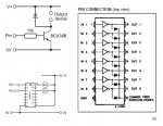
and then ULN2803 datasheet
http://www.rev-ed.co.uk/docs/ULN2803A.pdf
All the diodes are connected (pointy end) to V+.
e
Edit add Cross post with Hippy
From your post #1,
“Why are they brought out to a separate pin, would not internal connection to the 0v pin suffice?"
See about halfway down this page:
http://www.kpsec.freeuk.com/components/relay.htm
Protection diodes for relays
Then, Picaxe manual 3, pages 5 ,6 and 7
and then ULN2803 datasheet
http://www.rev-ed.co.uk/docs/ULN2803A.pdf
All the diodes are connected (pointy end) to V+.
e
Edit add Cross post with Hippy
Attachments
-
 41.5 KB Views: 19
Quite clear now thanks. It all started from my ( wrong ) understanding that the diode Ks were connected to 0v or rather the common pin was. But....
Thanks all.
Russ
.... it's so clear when you take the pin to +V or +V2.Nop ! I goobed!!
The pin is taken +V ( 28 pin project board). Page 2, digital output, shows the load with a back diode, and then qualifies it by using a 2803 without the diode.
Thanks all.
Russ
BeanieBots
Moderator
Hysteresis is when a point on operating curve is in a different position depending on which direction you come from. This is typical for many magnetic properties.I'm not sure what hysteresis means.
When an inductor/coil is disconnected (and I am going to explain it when it is mechanically disconnected), a large voltage difference builds up between the leads of the inductor by the residual current and/or magnetism, and it may arc across the air-gap between the disconnecting switch contacts or wires - in milliseconds or microseconds.
I think wires always have a number of fFs (0.001s of pFs) of capacitance.
Any conductor whatsover has both capacitance and inductance.
Test question:-
Design an LC circuit to resonate at a frequency that would give off light.
Calculate suitable L and C values. Then design the inductor and capacitor.
Will come upon an interesting problem. (great shame, would be fun to do!).
Inductors don't like a change in current. They will whatever they can to prevent it. If that means creating a stonking great big voltage to jump across the junction of your tranistor (or switch) when it turns off, then is that exactly what they will try to do.
The only reason the current in an inductor ever stops is because the energy gets dissipated. Either as I^2.R in the conductor, as load bang with light show as a spark or nicely into a snubber or freewheeling diode.
Make one out of superconducting material and the current will continue forever.
No, not really. Switchers work by using inductance as storage medium using different rates of current change to produce different voltages. 'Resisdual' current is something you really don't want in a switcher. It is current which cannot be converted (it's residual) and is therefore lost.That's how efficient switching regulators work, by using the residual current stored in the inductor to also put power into the output via a freewheel diode (schottkey in this case), after the transistor switches off when the output voltage reaches the selected level. Then when the output voltage falls below the selected voltage sharp, the transistor switches on again.
This transfers 85-90% of the input power wattage to the different- voltage output, unlike linear regulators, where the percentage is less.
Capacitors store voltage for a long time (about an hour depending on capacity).
Inductors store current (but dissipates it a lot more quickly).
A high efficiency switcher does NOT use diodes on the output. These are only used in low efficiency switchers. High efficiency ones use active rectification. 75% of the losses in a typical diode clamped switcher are lost in the diode.
The amount of time a capacitor can store energy has absolutely nothing whatsoever to do with its capacity. It will only lose charge if it has an internal leakage current or external load. (such as putting a meter on it to measure the voltage).
No. AFIK, the models in VSM do not simulate transients unless you specifically include items such as parasitic inductance in your model.Is this why I keep getting the yellow messages in PICAXE VSM saying "SPICE: transient GMIN stepping at time t=######"? SeeToo many iterations without convergence.
Too many iterations means the model is not converging to a steady state for your model. This may be because your model is too complex or has some errors. (reverse polarised electrolytic caps can cause it). There are parameters you can configure to help combat this issue but I am not familiar enough with it to advise on how to make those changes.
I think that's what I was trying to say, but didn't word it properly.beaniebots said:No, not really. Switchers work by using inductance as storage medium... typical diode clamped switcher are lost in the diode.