DAC linearity

geoff07

Senior Member
I'm just getting back into some Picaxe work after a long break doing other stuff. My first problem is to generate a sine wave. I want to be able to vary the frequency so prefer not to have to do too much filtering as with pwm, so I'm trying out the DAC capability for the first time. But in trying to get a decent sine wave on the scope I find that the DAC output isn't linear. My linearity test setup is as simple as could be so I'm perplexed.

Hardware is an 08M2 on an 08 proto board, powered by 5v, with the dac output directly connected to the scope with nothing in circuit except the probe

The pic shows the scope output from the code below. There are two problems:
- the range should be 0-5v but only 0-2.5v is displaying
- the graph should be a straight line but is seemingly geometric or exponential

Code:
 dacsetup %10100000 'dac enabled on ext pin with supply reference
 
 do 
    for B_temp = 0 to 31 
       daclevel B_temp 
    next 
 loop
2016-09-05 11.17.13.jpg

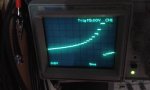
What have I overlooked?

I do recall seeing a fleeting mention of dac problems in some situations. But can't find a reference anywhere so may have imagined it. I get the same result on PE556 and PE6088.
 

hippy

Technical Support
Staff member
It was a long time ago when I tested the DAC output and various op-amp buffering but I do not recall any obvious or extreme non-linearity in the output.

Variance in command timing can give some appearance of non-linearity but that does not seem to be the case here.

My hunch would be that it is possibly an effect caused by the scope,r probes or other component interfering with the output. Is the download cable still connected ?

It would be worth doing a ramp down as well as a ramp up to check if that exhibits the same step levels. Probably worth trying a different 08M2 to see if it's the same.

I would try disconnecting the scope, outputting fixed DACLEVEL values, checking what voltage a meter reads and plotting those values. Compare to values seen with a scope attached. You can try $00, $07, $0F, $17, $1F for starters ...

Code:
#Picaxe 08M2
#No_Data

DacSetup %10100000
Do
  DacLevel $00 : Pause 5000
  DacLevel $07 : Pause 5000
  DacLevel $0F : Pause 5000
  DacLevel $17 : Pause 5000
  DacLevel $1F : Pause 5000
Loop
When I try that with a ~3.3V supply, uncalibrated meter, no capacitor on DAC output; 0.02, 0.73, 1.54, 2.34, 3.16. That seems to be roughly linear and as expected.
 

Buzby

Senior Member
Try putting a 1mS pause in the loop, see what happens.

Also, not directly related, the DACCON bits in the base datasheet for the PIC12F1840 do not seem to match the DACSETUP bits in PICAXE. ( Specifically the lack of external Vref-, which I was intending to use in a future project. )
 

AllyCat

Senior Member
Hi,

The "DAC" is basically a "160k potentiometer" (with 32 stepped positions) so its output impedance varies from about 5k at the extremes to 40k at the centre. Your first few steps look larger than in the middle and the 2.5 volts maximum output suggests that you have an ~5k load impedance (to ground) applied to the DAC pin. As hippy suggests, is the programming cable still connected (the serial output shares the same pin)? But 5k still seems unusually low, my USB-RS232 adapter is about 50k and I add a simple NPN emitter follower (to drive that) if I need higher performance from the DAC.

But what range of frequencies do you want to generate, I would have thought that a "partially filtered" 1024 level PWM signal might be no worse than the maximum 32 steps available from the DAC?

@Buzby: Yes, AFAIK the M2s (except 18M2) do not support an external negative reference voltage (see the ADCCONFIG command, referred to by the DACSETUP command).

Cheers, Alan.
 

geoff07

Senior Member
Doh! It was the download cable. I had assumed it would have a high impedance like the scope, but have never investigated what is in the thing. Thanks guys.

I'm making some simple audio test tones (sine waves) and one 08M2 is easier than a wien bridge or 555 with loads of components. If I can't get the frequencies I want with the dac I will of course try pwm, but then I have to do more filtering.
 

eggdweather

Senior Member
War story - when I left university, I was measuring the input voltage to an op-amp with a moving coil meter (AVO-8) and observed that as I changed the meter voltage scale that I'd get a different reading, this puzzled me for a while and I called over a technician who immediately looked at the circuit, looked at what I was doing and just said 'it's the meter, it's loading your circuit' then walked away - doh I was so embarrassed ... and I've never forgotten that moment :)
 

fernando_g

Senior Member
War story - when I left university, I was measuring the input voltage to an op-amp with a moving coil meter (AVO-8) and observed that as I changed the meter voltage scale that I'd get a different reading, this puzzled me for a while and I called over a technician who immediately looked at the circuit, looked at what I was doing and just said 'it's the meter, it's loading your circuit' then walked away - doh I was so embarrassed ... and I've never forgotten that moment :)
Indeed! the ohms per volt specification of those moving coil meters. Bit the rear end of more than one (myself included).
I remember distinctly when I first got my hands on a VTVM and its constant 10 Meg input resistance.....it was pure measurement Nirvana, warmup time notwithstanding.
 

premelec

Senior Member
And I changed my Heathkit VTVM to a CA 3030 op amp - no more warm up time and X10 feature battery op... Recently I've tested some cheap China multi meters on current ranges which indicate very large internal shunts so you get a big voltage drop across the meter when measuring current... always good to appreciate what measuring does TO measuring... you look at it you change it - but how much... ;-0
 

eggdweather

Senior Member
Yes, I have a Fluke 17B and on the mA setting some of my test circuits won't start, but if I move the current measurement to the 10A setting they work fine, it affects currents of about 100mA or more, so indeed there is an unwelcome and unexpected high shunt resistance on the mA setting.
One of the other tricks/tests I pickup up from an HP measurement class was to (if you can) always attach two scope probes to the circuit under test and observe the display when the second is attached, any waveform perturbations meant there was probe loading, a simple practical test that was based on experience I guess.
 
Top