Hi,
The current ohm-meter doesn't work properly, and it doesn't have a help file, so I came round to create a circuit mimicing of an ohm-meter. I am primarily doing this to help create another modelling primitive circuit that mimics the VTL5C6 analog optocoupler (LED and LDR) that I am going to post as well.
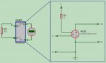
This is not an actual model, but it is a subcircuit with modelling-primitive circuitary that converts resistance (ohms) into micro-volts, or kilo-ohms into millivolts.
Basically, you connect the resistance (e.g. a voltage controlled resistor) you want to measure to the left side connectors, and the voltage difference between the right side connectors are connected to and read by a voltmeter.
If you set the voltmeter to micro-volts, it will read via the convertor subcircuit the resistance in ohms; if set to millivolts, it will read in kilo-ohms; if set to complete volts, it will read in mega-ohms.
I've attached an image of it as well so that users can preview what it is (including the ACCVS equation) before downloading the DSN.
EDIT: When you copy the sub-circuit into your design, make sure you copy what's in it's child sheet as well (if not already copied with the sub-circuit)
The current ohm-meter doesn't work properly, and it doesn't have a help file, so I came round to create a circuit mimicing of an ohm-meter. I am primarily doing this to help create another modelling primitive circuit that mimics the VTL5C6 analog optocoupler (LED and LDR) that I am going to post as well.
This is not an actual model, but it is a subcircuit with modelling-primitive circuitary that converts resistance (ohms) into micro-volts, or kilo-ohms into millivolts.
Basically, you connect the resistance (e.g. a voltage controlled resistor) you want to measure to the left side connectors, and the voltage difference between the right side connectors are connected to and read by a voltmeter.
If you set the voltmeter to micro-volts, it will read via the convertor subcircuit the resistance in ohms; if set to millivolts, it will read in kilo-ohms; if set to complete volts, it will read in mega-ohms.
I've attached an image of it as well so that users can preview what it is (including the ACCVS equation) before downloading the DSN.
EDIT: When you copy the sub-circuit into your design, make sure you copy what's in it's child sheet as well (if not already copied with the sub-circuit)
Attachments
-
 43.6 KB Views: 43
 -
87.9 KB Views: 11
Last edited: