Creating an 7 segment display clock using ws2801

Electronics Learner 123

Well-known member
Hi Guys,

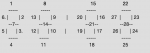
I have recently looked at this forum and others relating to controlling led strip ws2801 using a Picaxe chip, I have stumbled along this project here, this has really fascinated me and was wondering if there was a way to use an RTC to do the same thing, I have looked at the code that has been kindly distributed by the members of the Picaxe on how to code such things ,however, I don't understand it fully: is there a way to control 28 leds like this: (each number represents 1 led)

https://github.com/leonvandenbeukel/7-Segment-Digital-Clock/blob/master/7_Segment_Display with LED indexes 0 - 13 right segments - minutes.pdf


ps there will be dots in-between
EDIT: this is what I mean
23611


Could I implement something like seen here: https://github.com/leonvandenbeukel/7-Segment-Digital-Clock/blob/master/DigitalClockV2.ino
PS. This guy does other codes but they are all written for Arduino.

Is there a way that I could create an array for the numbers and call them when necessary; is it possible to stack e.g. RTC splits time from 12:30 into ---> 1 2 : 3 0 and then ----> code finds leds needed to light a 1, in digit 2: led 1 and 2 and 7 and 5 and 4 and then offset this by 7 so that it appears in the second digit while taking into account the dots in the middle of the time.

PS what chips would be needed and how would I wire them (diagram pls) , ps. I am very new so please bear with me :)

Thanks in advance
Electronics Learner 123
 

hippy

Ex-Staff (retired)
Welcome to the PICAXE forum.

It should be possible to do what you want to do. The WS2801 RGB strips can only be driven by the faster PICAXE-28X2/40X2 chips and the code is a little complicated but APA102 RGB strips can easily be driven by any PICAXE.so that would be the best preference. I would suggest PICAXE-14M2 as a minimum to give you enough I/O to handle the RTC, LED's and any buttons to set the clock and so on.

It would be possible to read an RTC and adjust the LED's so it displays the time. It is not worth worrying too much about how to actually achieve that now as it will all become a lot clearer once you start the project and start testing that you can control each LED.

If you divide the project up into a number of phases; reading the RTC, controlling the LED's, and bridging the two it should all fall into place. What sort of past electronics or programming experience have you had ?
 

lbenson

Senior Member
Taking the first digit only, do you have a mapping for what pattern of LEDs must be lit for each digit 0-9--numbered, for instance, 1,2,3,4,5,6,7 as per the first digit in your diagram?
You could represent these as a series of zero-terminated numbers in eeprom, e.g.
EEPROM 0,(1,2,3,4,5,6,0) ' "0"
EEPROM 7,(2,3,0) ' "1"
EEPROM 14,(1,2,7,5,4,0) ' "2"
. . .
EEPROM 56,(1,2,3,4,5,6,7); "8" (Note no zero termination)
EEPROM 63,(6,7,1,2,3,4,0); "9"
(Note that order doesn't matter and for ease of coding of the eeprom, I set up each digit to have 7 possible slots, one for each possible LED segment.)

Then suppose you decoded your 4 possible digits from your RTC into b4,b5,b6, and b7.

Code:
#picaxe 14M2
#terminal 9600

EEPROM 0,(1,2,3,4,5,6,0) ' "0"
EEPROM 7,(2,3,0) ' "1"
EEPROM 14,(1,2,7,5,4,0) ' "2"
' . . .
EEPROM 56,(1,2,3,4,5,6,7); "8" (Note no zero termination)
EEPROM 63,(6,7,1,2,3,4,0); "9" 

b4=1: b5=8: b6=2: b7=9 ' time of 18:29
for bptr=4 to 7 
  b8=@bptr ' get the value for this digit
  sertxd(#b8,": ")
  b9=b8 * 7 ' get the eeprom address for this value
  for b10=1 to 7
    read b9,b11 ' get led segment to light
    inc b9      ' move to next digit
    if b11 = 0 then: exit: endif ' if we've reached the end, quit
    b12= bptr-4*7+b11 ' this is the proper LED segment for this digit
    sertxd(#b12," ") ' this prints the segment number for debugging purposes
    ' Now do what you need to do to light this LED
  next b10
  sertxd(cr,lf)
next bptr
This will run in the simulator and give the proper LED segments for the value specified: 18:29. The trick is that for each digit, any LED segment is 7 greater than the corresponding LED segment in the previous digit. You can single-step through the code in the PE6 simulator to see what is happening.
Code:
1: 2 3 
8: 8 9 10 11 12 13 14 
2: 15 16 21 19 18 
9: 27 28 22 23 24 25
(Note: not thoroughly tested; and you should replace register numbers (b4-b12) with meaningful names.)
 

Electronics Learner 123

Well-known member
Ibenson & Hippy, thank you for you quick support.

Would there be a way to use a wifi module e.g. esp8226 to pull the time from a server and display this so that I wouldn't have to use an rtc etc...

Also are there examples of Picaxe iOT projects that use a website to control the Picaxe board e.g. turn an led on/off so that I could implement this in my project to change the time function to the date: for example.

ps, is there any update on a 64-bit axe pad for Mac.

Kind Regards
Electronics Learner 123
 
Last edited:

Electronics Learner 123

Well-known member
Hi Everyone, I have decided to use apa102 instead as I understand that these are the best to use,

I don't quite understand the code above, I have looked through the README on the apa102.zip that has been kindly provided, however how and what does the EEPROM function do.

My main question is how would I go about this:
From the RTC(ds3231), I find that the first mins equal to 14, how would I split this number up into a separate 1 and 4,
How would I then offset their position without effecting the position of any other leds on the strip. (e.g. offset 1st 3 by 1, but the 4th, 5th , 6th etc remain in their place?

Electronics Learner 123
 

lbenson

Senior Member
what does the EEPROM function do
See the EEPROM (DATA) statement in Manual 2. This stores values in non-volatile memory (survives power cycling). In the above program it's used to store which LED segments are lit for each digit 0-9. 0, 1, 2, 8 and 9 are provided--you would need to fill in the eeprom values for 3-7. Map it out with pencil and paper if need be.

From the RTC(ds3231), I find that the first mins equal to 14, how would I split this number up into a separate 1 and 4,
See the bintoascii command. Don't know about your other question about how to drive the LEDs.
 

AllyCat

Senior Member
Hi,
mins = 14 .... how would I split this number up into a separate 1 and 4,
Particularly for two digit numbers it can be easier and more efficient to simply divide by 10 and also take the remainder after dividing by 10 :
For example: b3 = mins / 10 : b2 = mins // 10 . Larger numbers are also possible, but you (also) may need to consider if you want to display (one or more) leading zeros.

Cheers, Alan.
 

hippy

Ex-Staff (retired)
If you read an RTC into three 'h', 'm', 's' variables and the time is 12:34:56 the 'h' variable will end up set to $12, 'm' set to $34, 's' set to $56. You can simulate that with -
Code:
h = $12
m = $34
s = $56
You can convert those to hours most significant digit, hours least significant digit, minutes most significant digit, minutes least significant digit, seconds most significant digit, and seconds least significant digit -
Code:
hMsd = h / $10
hLsd = h & $0F
mMsd = h / $10
mLsd = h & $0F
sMsd = h / $10
sLsd = h & $0F
You can then convert those into the segments required for each digit -
Code:
Read hMsd, hMsdSegs
Read hLsd, hLsdSegs
Read mMsd, mMsdSegs
Read mLsd, mLsdSegs
Read sMsd, sMsdSegs
Read sLsd, sLsdSegs
When you come to output to the APA102 you would then map what is sent to the segment bit which that LED represents, for example, but it would need to be adjusted for the order you have the LED strip wired -
Code:
UpdateLeds:
  Head
  Send(hMsdSegs, SEG_A) ; Set hMsd
  Send(hMsdSegs, SEG_B)
  Send(hMsdSegs, SEG_C)
  Send(hMsdSegs, SEG_D)
  Send(hMsdSegs, SEG_E)
  Send(hMsdSegs, SEG_F)
  Send(hMsdSegs, SEG_G)
  Send(hLsdSegs, SEG_A) ; Set hLsb
  Send(hLsdSegs, SEG_B)
  :
  :
  Send(sLsdSegs, SEG_F)
  Send(sLsdSegs, SEG_G)
  Tail
  Return
And that can all be done via SYMBOL definitions and #MACRO -
Code:
;               .ABCDEFG
Symbol SEG_A = %01000000
Symbol SEG_B = %00100000
Symbol SEG_C = %00010000
Symbol SEG_D = %00001000
Symbol SEG_E = %00000100
Symbol SEG_F = %00000010
Symbol SEG_G = %00000001
Code:
; Send a four byte packet out via HSPI
#macro SendPacket( n1, n2, n3, n4 )
  HSpiOut( n1, n2, n3, n4 )
#endmacro

; Send the start of data header
#macro Head()
  SendPacket( $00, $00, $00, $00 )
#endmacro

; Send a LED controlling command
#macro Send( var, mask)
  tmp = var & mask Max 1 * BRIGHTNESS
  SendPacket( $FF, tmp, tmp, tmp )
#endmacro

; Send the end of data tail
#macro Tail()
  SendPacket( $FF, $FF, $FF, $FF )
#endmacro
 

Electronics Learner 123

Well-known member
How do the packets work?
If you read an RTC into three 'h', 'm', 's' variables and the time is 12:34:56 the 'h' variable will end up set to $12, 'm' set to $34, 's' set to $56. You can simulate that with -
Code:
h = $12
m = $34
s = $56
You can convert those to hours most significant digit, hours least significant digit, minutes most significant digit, minutes least significant digit, seconds most significant digit, and seconds least significant digit -
Code:
hMsd = h / $10
hLsd = h & $0F
mMsd = h / $10
mLsd = h & $0F
sMsd = h / $10
sLsd = h & $0F
You can then convert those into the segments required for each digit -
Code:
Read hMsd, hMsdSegs
Read hLsd, hLsdSegs
Read mMsd, mMsdSegs
Read mLsd, mLsdSegs
Read sMsd, sMsdSegs
Read sLsd, sLsdSegs
When you come to output to the APA102 you would then map what is sent to the segment bit which that LED represents, for example, but it would need to be adjusted for the order you have the LED strip wired -
Code:
UpdateLeds:
  Head
  Send(hMsdSegs, SEG_A) ; Set hMsd
  Send(hMsdSegs, SEG_B)
  Send(hMsdSegs, SEG_C)
  Send(hMsdSegs, SEG_D)
  Send(hMsdSegs, SEG_E)
  Send(hMsdSegs, SEG_F)
  Send(hMsdSegs, SEG_G)
  Send(hLsdSegs, SEG_A) ; Set hLsb
  Send(hLsdSegs, SEG_B)
  :
  :
  Send(sLsdSegs, SEG_F)
  Send(sLsdSegs, SEG_G)
  Tail
  Return
And that can all be done via SYMBOL definitions and #MACRO -
Code:
;               .ABCDEFG
Symbol SEG_A = %01000000
Symbol SEG_B = %00100000
Symbol SEG_C = %00010000
Symbol SEG_D = %00001000
Symbol SEG_E = %00000100
Symbol SEG_F = %00000010
Symbol SEG_G = %00000001
Code:
; Send a four byte packet out via HSPI
#macro SendPacket( n1, n2, n3, n4 )
  HSpiOut( n1, n2, n3, n4 )
#endmacro

; Send the start of data header
#macro Head()
  SendPacket( $00, $00, $00, $00 )
#endmacro

; Send a LED controlling command
#macro Send( var, mask)
  tmp = var & mask Max 1 * BRIGHTNESS
  SendPacket( $FF, tmp, tmp, tmp )
#endmacro

; Send the end of data tail
#macro Tail()
  SendPacket( $FF, $FF, $FF, $FF )
#endmacro
What do the packets do? And do the n1,n2,n3,n4 represent: are they the digits and could you also explain how to macro and symbols with the binary work?

Electronics Learner 123
 

lbenson

Senior Member
The best thing for you to do to get a feel of it is to put code in the simulator and step through it. You can assign values like "h = $12 : m = $34 : s = $56"
and walk through the code which converts them from BCD (the form in which the RTC returns them) into separate binary values, and then into 6 separate values representing the digits in binary.

Then you can walk through the code which reads the eeprom to see which of the LEDs shown in your diagram in your first post is to be lit in sequence. Depending on how the LED strip works, you may want to arrange it so that the series of numbers you get is in reverse order, 28-1.

In PE6, under "Workspace Explorer", "Settings", "Simulation options" you can click the box to simulate the DS1307 RTC, so you can even work with the current time.

This would be a good exercise which would take you through many of the steps you would need to perform to achieve your goal, and would give you some familiarity with how to program in PICAXE basic.
 
Top