Converting a digital keypad to an ADC keypad

adamg

Member
For my robot arm project, I have a keypad:

I want to use it with the AXE031 servo controller, with an 18m2 chip. I really want to save on pins, so have decided to try and make an ADC circuit using resistors.

I found a really helpful link on this forum about building an ADC circuit - however, they were talking about detecting multiple key presses etc! Above my ability at the moment. Anyway - their circuit design really helps! It is here:

So because of my lack of experience in programming and electronics, I have a question about the programming part.

1) If I use the ADC command for this circuit how does the ADC know how many resistors there are to start with and get the result from 0 - 255?

So if it passes through a 10k resistor - what would the ADC read it as? If it passes through two 10k resistors and one 3.3k resistor what is the result? I think the maximum resistors it can pass through on this circuit is if you press number 1 on the keypad. It should pass through three 10k resistors and two 3.3k resistors. the minimum would be pressing the hash key which passes though no resistors.

I am sorry for my lack of knowledge on this and have read a lot of stuff about using photometers with the ADC but am struggling to find an answer about using it with resistors.

Thanks in advance if anyone can point me in the right direction :)

Adam :D
 

Paix

Senior Member
Resistor shopping: Figure out the most popular values that you are likely to use and buy a bandoleer of 100, it won't break the bank and bit by bit you end up with ( a full bits bin ) a stock of most popular values which you might need. Hopefully enough to keep you productive. Then you only need to do regular shopping for another 100 and the really interesting components.

On my last shop, I noticed that Tech Supplies had, apparently, stopped offering 18M2+ in fives with a small incentive. I still bought five, but didn't smile quite as much. :)
 

adamg

Member
@Paix,

This was my first time resistor shopping :) Thanks for the tips!

I got a bunch of 3.3k, 10k and 33k resistors :D The electronics store isn't too far luckily as I can see it would be handy having more of a selection as Paix pointed out.

So, I build the ADC circuit. I started at 6:30 in the morning and have just finished - nearly 10pm! haha, I know it is simple, but this was my first breadboard project, so I guess I have an excuse :p

My first attempt failed, but on second attempt, it worked. I rigged the whole thing up to a servo and plugged it into the AXE031 servo controller.

The hardest part was researching how to do the programming. But Westaust's tutorials on using ADC for reading a pot, helped a lot! Thanks for that. Also I wouldn't had got anywhere without all the super fast advice people have given me! Thanks!!! You are all amazing people :D

I used this for the circuit:

Cheers guys!

If I press a number, the servo twitches that number of times. Star twitches 5 times and hash twitches 4 times. zero moves once slowly.

There is a lot of unneeded code in there >___< I am still learning to program the AXE031 (Or any picaxe for that matter!!! hehe) For example, once the speed is set for a servo, it doesn't need to keep being set, unless you want to change the speed. (Just found this out this evening)

I will post half the code - as it says it is too long for this forum - but the button labels are just copies of the twitch move - lots of them haha!

Code:
i2cslave $C2,i2cslow,i2cbyte ' Join i2c with SD21 
                                         
          init:
          let b1 = 0
          
          start:
          let b1 = 0
          pause 10
          readadc c.2 , b1
          PAUSE 10
          if b1<120 then start
          if b1>120 then BUTTONPUSH
          
          
          BUTTONPUSH:
          readadc c.2 , b1         'read value on pin c2 into variable b1
          pause 10           	    
          if b1>240 then buttonhash
          if b1>215 then button0
          if b1>199 then buttonstar
          if b1>182 then button9
          if b1>175 then button8
          if b1>159 then button7
          if b1>150 then button6 
          if b1>145 then button5
          if b1>134 then button4
          if b1>130 then button3
          if b1>125 then button2
	    if b1>120 then button1       
	    if b1<120 then start    	 
	    goto start  


          BUTTON1:
            i2cwrite 63,(225)       		' servo 1 twitch once 
            pause 100
            i2cwrite 0,(50)                       ' half speed
            i2cwrite 63,(110)                     
            pause 150    
            goto start
            
          BUTTON2:
            i2cwrite 63,(225)       		 
            pause 100
            i2cwrite 0,(50)                        
            i2cwrite 63,(110)                     
            pause 150 
            i2cwrite 63,(225)       		' servo 1 twitch twice 
            pause 100
            i2cwrite 0,(50)                       ' speed 
            i2cwrite 63,(110)                     
            pause 150    
            goto start
           
          BUTTON3:
            i2cwrite 63,(225)       		' servo 1 twitch three times etc. 
            pause 100
            i2cwrite 0,(50)                       
            i2cwrite 63,(110)                     
            pause 150
            i2cwrite 63,(225)       		 
            pause 100
            i2cwrite 0,(50)                        
            i2cwrite 63,(110)                     
            pause 150 
            i2cwrite 63,(225)       		 
            pause 100
            i2cwrite 0,(50)                        
            i2cwrite 63,(110)                     
            pause 150     
            goto start
           
            
	    BUTTON4:
            i2cwrite 63,(225)       	
            pause 100
            i2cwrite 0,(50)                        
            i2cwrite 63,(110)                     
            pause 150  
            i2cwrite 63,(225)       	
            pause 100
            i2cwrite 0,(50)                        
            i2cwrite 63,(110)                     
            pause 150 
            i2cwrite 63,(225)       		
            pause 100
            i2cwrite 0,(50)                      
            i2cwrite 63,(110)                     
            pause 150 
            i2cwrite 63,(225)       	
            pause 100
            i2cwrite 0,(50)                       
            i2cwrite 63,(110)                     
            pause 150   
            goto start
           
            
          BUTTON5:
            i2cwrite 63,(225)       	 
            pause 100
            i2cwrite 0,(50)                       
            i2cwrite 63,(110)                     
            pause 150  
            i2cwrite 63,(225)       		 
            pause 100
            i2cwrite 0,(50)                        
            i2cwrite 63,(110)                     
            pause 150 
            i2cwrite 63,(225)       	
            pause 100
            i2cwrite 0,(50)                       
            i2cwrite 63,(110)                     
            pause 150 
            i2cwrite 63,(225)       	
            pause 100
            i2cwrite 0,(50)                       
            i2cwrite 63,(110)                     
            pause 150 
            i2cwrite 63,(225)       		
            pause 100
            i2cwrite 0,(50)                     
            i2cwrite 63,(110)                     
            pause 150   
            goto start
           
    (And so on - the rest of the code is all copies of the above - with more twitches)
           
            
            end
 

adamg

Member
Hello again :)

So detecting the keys all worked fine. However, because of my lack in experience and programming skills, I ran into problems yesterday when I continued programming, trying to make the program store the numbers into variables, to add together. For example, when I type a single number, it is fine. But if I want 10, 11, 12 etc. I ran out of 'IF THEN' things in the stack or something. It said I can only have 20.

Does anyone know of a different way? I was storing the variable typed. Then using lots of 'IF b1' blah blah.. Then go back and store the next key into a different variable, then use both variables to make a number.. I am sure their must be a better way? My way just used too many IF THEN's..
 

bfgstew

Senior Member
This was given to me and it works well, you may have to adapt it slightly to suit yourcode but it should do what you want.

Code:
 	For b12 = 1 to 4				
  			Gosub GKP  			
                                      w8 = w8 * 10 + b1 
  			serout B.7,N2400,(254,159,#w8,"ms")
  		pause 30
  			next b12
The for b12 = 1 to 4 is how many numbers you want, change the 4 to suit how many you want.
w8 is the word variable you are putting the numbers into,change w8 to whatever variable you wish.
Gosub GKP is to jump to the keypad code to read what number is pressed on the keypad.
The serout B.7,N2400 bit it to send the data to LCD, or OLED to show what you have pressed.

Hope this helps?

Stewart
 

adamg

Member
@bfgstew:

Thanks man! I will try and figure this out this afternoon :) I am at work, so will keep coming back to it on my breaks. I hope I can figure it out, as it may seem simple, but I don't even know what 'FOR' does! hehe :) I will hit the manuals! :D Cheers for nudging me in the right direction man :)
 

adamg

Member
My goodness, I am a slow learner! haha :) I think I have my head around it now! :D (2 days later)

Bfgstew - I think I see what you're getting at. I will do a bit of experimentation! Thanks again!
 

bfgstew

Senior Member
Can anyone help on this subject? I came across this site and was very impressed with the results from his schematic, now unfortunetly I cannot seem to get the schematics back up, they are just blank pages, does anyone get the same? Would love to try this circuit out.
 

AllyCat

Senior Member
Hi Stewart,

There appear to have been only 16 downloads (of the pictures) in the last 19 months, so probably not too promising; the files appear to be linked to an external (not responding) website. :(

However, the principle is simple enough, but the exact design will depend on the (acceptable) ratio of hardware to software simplicity.

Personally, I would wire resistors of perhaps 1k between rows 1-2, 2-3 and 3-4 of the keypad, with row 1 to ground. Then, say, two 3k9s between pairs of adjacent columns. These resistor values could be scaled as required, for example you might use two 2k2 (or 3k3, 4k7, etc.) in parallel for each "row chain resistor" and two (of the same value again) in series for each "column chain resistor".

Now you need to feed a current to column 3, ideally a "contant current" source, but a resistor of >>10k to the supply rail should be useable. Perhaps even 100k or higher, to give a reasonably constant current and still give resolvable A/D values (particularly using READADC10) on column 3.

With the arrangement described above, the "key mapping" typically should be 1,4,7,#,2,5,8,0,3,6,9,*, no key) but the resistors could be configured dfferently if required. Note this will only work with one key at a time pressed, although a few specific "multiple keyspressed" combinations might be possible, depending on the resistor tolerances (and software design), etc..

Cheers, Alan.
 

premelec

Senior Member
My solution was:

KeyPad_3192.jpg I posted this long ago and it's worked well - best not to rely on constant contact resistance of buttons - they vary some so a range of values may occur -
 

bfgstew

Senior Member
Thanks Premelec

I am breadboarding this at the moment so I can see what system gives the best and most constant results.

There does seem to be a typo on the schematic though - the 1N547A Diode, in the data sheet it states a 1N457A.
Now I cannot find a 1N457A from my usual supplier is there an equivalent I could use?
 

AllyCat

Senior Member
Hi Stewart,

I suspect that any normal silicon diode will do fine, e.g. 1N4148 or whatever you have to hand. I would have thought that the LM334Z might be more of a problem.

The "constant current" drive will indeed ensure that the voltages measured correlate well (i.e. linearly) with the resistance values. But perhaps rather "overkill" for a simple 12 button keypad. Personally (unless working in a "noisy" environment and/or with long cables), I would just try using a high value resistor (perhaps ten times the resistance being measured across, so >100k) from the supply rail. Use readadc10, but you only need to work with the low byte (scaled by multiplication/division) to create 13 unique integer values for the "lookup".

Cheers, Alan.
 

bfgstew

Senior Member
Thanks e and Alan,

Sussed out the 1N4148 replacement.
I understand where your coming from Alan, it does seem overkill, but for the sake of a few pence for the LM334Z a diode and a bunch of resistors I want to see how well this set up performs as all the other resistor matrix set ups all seem to be very close to each other in values and I feel something better needs to be done, that is a bit more reliable. As I said it is just breadboarding for now and shall see what results come out of it, so we can compare, then decide on which rooute to take.
 

premelec

Senior Member
@bfgstew - note that when you use the constant current circuit producing accurate voltages [you hope..] your PICAXE ADC voltage measurement must also be accurate. When you use just resistance changes to indicate keypress [as circuit I showed in post #18] it's ratiometric with the PICAXE supply voltage which so supply voltage changes won't affect the READADC value. Sometimes this is an advantage...
 

bfgstew

Senior Member
Valid point Premelec.

I shall do a thorough camparison of both set ups and then can see advantages/disadvantages.

I have read no end of threads on 1 wire set ups using the resistor set up and always find that at some point in the scale the voltage readings at the lower end do tend to get very close to each other which, with lots of factors can lead to errors in readings. I am hoping that this set up, albeit, as Alan (Allycat) pointed out is rather overkill (another valid point) but if it removes errors and gives a uniform voltage reading between each keypress then for the sake of a few more components, it must be worth a try.

Will keep you posted on the outcome.
 

AllyCat

Senior Member
Hi Stewart,

Yes, premelec puts that very elegantly. I was preparing a reply yesterday which tried to say much the same, but it was becoming so lengthy and complex that I abandoned it. However, perhaps it's worth me posting it anyway, now that it might be clearer what I was trying to say. :)

... I feel something better needs to be done, that is a bit more reliable.
[jumps on hobbyhorse]There are various aspects to "reliability", for example:

(1) Does it work (always, reliably) "out of the box", (e.g. when built according to a circuit diagram)?
(2) Can it be "calibrated" to work well?
(3) Will it continue to work properly (with variations of supply voltage, temperature, etc.)?

Now, (1) can be quite difficult to achieve, particularly with analogue circuits, it's one of reasons for the existence of 1% resistors, precision Op-Amps and "complicated" circuit designs, etc..

So (2) is one reason why you may find circuits with "Pots" sprinkled all over the place. But (IMHO) for PICaxe there is a far better solution, you can just store "calibration" data in the EEPROM, as required.

(3) Is (or should be) a "minimum" target, but circuits unlikely to achieve this are regularly to be found on internet/forum postings. However, electronics components are often much better than their "worst case" specification, so sometimes practice can work better than theory suggests. :)

Perhaps surprisingly, the LM334Z design is probably NOT the best way to achieve (1). My reasoning is:

The PICaxe A/D converter (normally) calculates the "voltage" relative to the supply rail, which it does extremely well. Anything which is not referenced to the supply rail thus introduces an "error". Of course you can use the PIC's internal FVR and/or a regulated supply rail, but both of these also have "errors" (or tolerances), maybe only a few percent but still needing to be considered. The voltage variation of Alkaline batteries (over their life) is of course truly "horrible".

The "constant" current delivered by the LM334Z depends on its internal reference circuit (which the data sheet says is about +/- 6%) and the external calibration resistor (typically +/- 5%), thus the actual current may be about +/-10%. That's "worse" than a (5%) resistor feeding current from the supply rail, so a simple resistor divider chain from the supply rail may actually work better than an "exotic" current source, if trying to achieve (1) above.

However, a simple resistor feed has "issues" as well. When the voltage measured across the keyboard increases (if pressing higher-numbered keys) the current falls, so the size of the voltage steps reduces. My "solution" was to keep the voltage low (high value of resistor to the supply rail), and you may note that premelec's design uses 3k3 and 3k6 resistors (the 3k6 to compensate for the lower current).

IMHO the important thing is to analyse/measure the operation of the circuit properly. For example, initially scale the A/D values so that you get at least 10 digits rise for each step (e.g. 0, 11, 21, 30, 39 ...) Then you can examine the exact values, to see what "offset" to add (e.g. 5) and what divisor to use to get a "clean" integer series for the lookup. For example: adval = adval + 5 would produce the series 5, 16, 26, 35, 44.... from the above series, which when divided by 10 (and truncated by PICaxe's integer divison) becomes the desired 0, 1, 2, 3, 4....
[/hobbyhorse]

Cheers, Alan.
 

bfgstew

Senior Member
Audientes Discant

This is why I like this site so much! Alan, thank you for pointing out the possible errors and pitfalls, I am taking on board all that is said.
Now me being me, I am still going to have a play with the concept, not to spite you, but to help me learn. The outcome may be better than we thought, it may not, as the old saying goes - curiosity killed the cat - I am hoping it doesn't kill me, but at least teach me a little more and hopefully pass some useful info onto others who wish to take from it what they want.

Thanks for all the pointers, it really is most appreciated.

Stewart
 

bfgstew

Senior Member
Right, tested the circuit on breadboard before putting onto some strip board and these are the results.

KEY-DMM-READADC

1-0.434v-22
2-0.215v-11
3-0.622v-31
4-1.125v-57
5-0.906v-46
6-1.312v-66
7-1.815v-92
8-1.597v-81
9-2.004v-102
*-2.498v-130
0-2.281v-118
#-2.685v-136

NO KEY PRESS = 4.65v

This was tested just using a simple READADC loop, but the results were very consistant on every press. now to put it into a full sub routine for getting key values onto an OLED, and see how well it performs then, but so far, looking good.
 

AllyCat

Senior Member
Hi Stewart,

Hmm, doesn't look too good to me. :(

The "row" and "column" resistor values don't look very well matched; for example the jump from 66 to 81 might be a problem. The last values 102 - 118 - 130 - 136 might be tricky as well. But I haven't actually plotted the values to see if an acceptable "line fit" can be achieved.

I also note that there is no zero volts value. That's one value that normally can be "guaranteed" to be correct. :)

I'm not saying that it won't (or can't be made to) work, but it's certainly not to my definition of "reliability" in #25 - (1) above, nor perhaps even (2).

Cheers, Alan.
 

premelec

Senior Member
@bfgstew - your measured values look workable if you simply bracket READADC values +/- 8 for instance - in short if the read value is > A and < B then it's a #AB where the A to B spread is 16. You aren't going to get linear output from the circuit... That's a little awkward in code but seems to work ok.
 

bfgstew

Senior Member
I found a slight error in the last test on the keypad values, forgot I still had keypad wired up for 7 pin usage so it still had 7, 330 ohm and 3, 10k ohm resistors in circuit..........................DOH.

SO re did readings and they look pretty good.

1 = 0
2 = 12
3 = 24
4 = 36
5 = 48
6 = 60
7 = 71
8 = 83
9 = 94
* = 106
0 = 118
# = 130
No keypress = 242

Much more consistant readings.

Now to code this lot up, which is not my strong point, has anyone got any pointers to a nice keypress routine I code study and adapt to suit my needs?
 

hippy

Technical Support
Staff member
Now to code this lot up, which is not my strong point, has anyone got any pointers to a nice keypress routine I code study and adapt to suit my needs?
Should be quite easy. First find the mid-points between your readings 1 to 2 is 6, 2 to 3 is 18 etc, then turn that into a SELECT-CASE putting the desired key press value into b1 ...

ReadAdc <PIN>, b0
Select Case b0
Case < 6 : b1 = 1
Case < 18 : b1 = 2
:
Case < 124 : b1 = 0
Case < 140 : b1 = #
Else : b1 = No keypress
End Select
 

AllyCat

Senior Member
Hi Stewart,

Yes that data is much more what I would have expected from the current-source drive, but I still believe that a simple resistor should be sufficient (or even better).

The method I would use with that virtually "straight line" data is with, for example :

keynumber = adcvalue + bias * scale1 / scale2 to produce a number from 0 to 12.

Then to "map" the keys (if not in the correct sequence) or to show the actual characters use :
lookup keynumber,("1","2","3","4","5","6","7","8","9","*","0","#"),character
or control the "program flow" with:
on keynumber goto ..... , on keynumber gosub .... , if keynumber = .... . etc..

For your values, "scale1" can be ignored (i.e. = 1), "scale2" would be 12 and "bias" either 6 or 7.

For a system that would "always" work "out of the box" (with suitably-designed hardware), personally I might include a little block of code that asks, for example: "Press key 0" the first time that it runs, then calculates "scale2" and stores it in the EEPROM. "bias" and "scale1" probably could be constants (typically 6 and 10) dependent on the exact hardware design ;)

Cheers, Alan.
 

premelec

Senior Member
@hippy - thanks for that code - so straightforward compared to my previous coding - [I still like ratiometric rather than voltage accurate setup]...

@Allycat - you are pretty clever too!
 

bfgstew

Senior Member
I used Hippys code and it works perfectly, still going to test reliability, just to make sure but we are going in the right direction.

Thanks Alan for your suggestion, will keep it in my projects folder until I am better experienced with higher level coding!

Code:
	do 
		readadc B.7,b0
Select Case b0
Case < 6 : b1 = 1
Case < 18 : b1 = 2
Case < 30 : b1 = 3
Case < 42 : b1 = 4
Case < 54 : b1 = 5
Case < 65 : b1 = 6
Case < 77 : b1 = 7
Case < 89 : b1 = 8
Case < 100 : b1 = 9
Case < 112 : b1 = "*"
Case < 124 : b1 = 0
Case < 140 : b1 = "#" 
Else : b1 = ""
End Select	
	loop until b0 < 200
	return
The only problem is getting the characters * and # to display directly from a keypress, i get 42 if I press * and 35 if I press #?????????
 

AllyCat

Senior Member
Hi Stewart,

You probably just need to remove the # in the sertxd output instruction.

Code:
b1 = 35     ; "#"
b2 = 42     ; "*"
sertxd(b1," ",#b1," ",b2," ",#b2)        ; Displays:  # 35 * 42
Cheers, Alan.
 

hippy

Technical Support
Staff member
The only problem is getting the characters * and # to display directly from a keypress, i get 42 if I press * and 35 if I press #?????????
You are seeing the ASCII values of * and #. As AllyCat says, removing the # in your SERTXD will solve that, but then when you press 0 to 9 you won't get what you want !

You need to either hold all key presses as ASCII and then convert to digit values when you come to process digits, or hold them as numeric and then handle them differently when you come to display them -

Code:
If b1 > 9 Then
  SerTxd( "Press = ", b1 ) ; ASCII
Else
  SerTxd( "Press = ", #b1 ) ; Digit value
End If
Your b1 = "" may also prove problematic. This is equivalent to b1=0 which is the same as pushing keypad zero.
 

AllyCat

Senior Member
Hi Stewart,

Perhaps I should have summarised my proposal in #33. If you "plug" your keypad A/D value into the following formula (code) it should give a numerical (integer) value from 0 to 11 (or a larger number if no key is pressed) which you can use in any ON GOxxx ... , LOOKUP ... , IF ... or CASE ... statement in your program :

keynumber = adcvalue + 6 / 12 :)

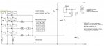
As primarily a "hardware engineer" I've been considering what could be the "best" hardware arrangement to use with a 4 x 3 keyboard (since I haven't been impressed with any of the designs I've seen so far). I've even tinkered with a few values in a spreadsheet, not a "fully engineered" design, but I've now a fair idea what I'd breadboard if/when I need an analogue keypad:

Firstly, a "constant-current source" should only be used if there is a regulated (5 volt) power supply rail. With an unregulated supply, the A/D reference could/should use the internal FVR (Fixed Voltage Reference) but that's probably a case of "Out of the Frying Pan into the Fire" for most users. Personally, I try to design my PICaxe hardware to work not only with 3 x fresh alkaline cells, but 3 x NiMH (or not-so-fresh alkalines) and ideally two cells (since many of my projects are to interface with devices which are powered by only 2 AA cells).

So, what resistor values to use across the keyboard columns and rows? Well, Microchip "recommend" that the A/D converter should be driven from a source impedance of less than 10 kohms. That "suggests" that each keyboard resistance step should be just under 1 kohm, let's assume 1 kohm for now; higher impedances can be used, e.g. if a capacitor is added to the A/D pin (not a bad idea anyway). That would make the "row" resistors 3k0, which is a "preferred" (standard) value, but only from the "E24" series, not very common, so more on that later.

Now what about the pullup resistor? One issue is that the "higher" keypad numbers put a higher resistance load on the pullup, so the current (and thus voltage steps between adjacent keys) are smaller. A design linked earlier in this thread uses 10k (with 10k "row" resistors) which IMHO is far too low. At the other extreme, the text in the linked spreadsheet suggests 1 Mohms (rather high), so perhaps my "wet finger in the air" 100k value earlier wasn't too far out!

However, another factor helps to make a decision: Normally, it's necessary to repeatedly read the A/D conveter to see if a key has been pressed (or additional hardware could be added). But if we make the ratio of the pullup to keyboard resistors large enough then it can be used as a digital input. Thus it can be read directly in an IF pin... statement, or even generate an interrupt! The base PIC datasheet says that the maximum logic "zero" level is 15% Vdd, so if the highest "keypressed" resistance is 11k then the pullup should be greater than (11 * 85 / 15 = 62) , say 68 kohms. Another advantage of the relatively high resistance ratio is that we can read the pin using READADC10 but only need to work with the low byte.

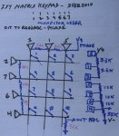
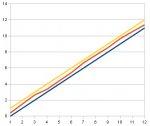
Therefore my "first cut" design was a 1k resistor between each adjacent pair of columns, 3k0 between each adjacent row and 68k pullup from the keyboard/PICaxe pin. The spreadsheet showed that the "rollover" (due to increasing resistance values at high keynumbers) gives a just about acceptable fit to a straight line, but can we do better (and get rid of those 3k0s)? My spreadsheet suggests that 2k7 from row 1 (key 1) to row 2 and 3k3 between each of the other two adjacent pairs of rows gives a better fit. For example see the Red line between the Blue and Yellow thresholds, below.

For an analogue design of this type it's important to use "exact" resistor values which can be inconvenient to obtain. However, a feature of the preferred (E6, E12, E24) resistor series is that the operation is very similar if all the values are changed by the same number of steps. For example, the 68k pullup could be changed to (perhaps a more available) 100k, with keypad chains of 1k5 + 1k5 and 3k9 + 4k7 + 4k7. Note that 3k9 can be fabricated by connecting 4k7 and 22k (which should be in most spares boxes) in parallel. Another possible set of values is 47k (pullup) with 680R (ohms) + 680R and 1k8 + 2k2 + 2k2 (where the 1k8 could be 2k2 in parallel with 10k and/or the "47k" = 2 x 22k in series).

Even lower resistor values might be possible, but we need to consider the resistance of the keypad switches. Mine measures about 30 ohms, but nearer 60 ohms if only lightly pressed. It won't affect the resistor chain current much, but it would be wise to make the smallest chain "step" resistance at least ten times the "contact" resistance.

As mentioned before, it's not possible to guarantee that these designs will "work out of the box" using 5% resistors. It might be possible by improving just the pullup to 1% tolerance, because that primarily defines (or should) the current in the resistor chain. But the calculation is complex and it's easier (and success more likely) to include a "calibration" stage in the software. That could be as simple as reading/displaying the A/D voltage when the "0" key is pressed and then selecting the scale factor(s) in the program such that the value is equi-distant from the * and # "decision thresholds" (i.e. to produce a value of "10.5" after the final division). The "bias" (or sit-up) value may also help optimisation but can probably be preset at between 1/4 and 1/2 of the average keyboard voltage step.

A-D_keypad.jpg

Cheers, Alan.
 

bfgstew

Senior Member
Many thanks Alan for your valuable and concise input on this thread, to be honest the whole thing has become a bit like finding the holy grail, why isn't there a simple 'out of the box' keypad on the market? 4x3, 4x4 keypad with 1 wire, hook it up and away you go, beats me, especially with the amount of pins these keypads take up.
Now the original thread was from The Backshed forum and a guy by the name of Jez Siddons, his circuit is the basis of this and it gives a virtual straight line to work with, which is a huge bonus, but, and its a big but for me, his code is in MMBasic, can this be transposed into C, simply or is it a complete re write?
This is the thread with the afformentioned coding if you wish to study it.
I do have the keypad running using Hippys code, it does work, but it is not 100% reliable, now that is not down to Hippys code, I have it wired up on breadboard so there is going to be a certain amount of unseen fluctuations/resistances in the circuit, it is on 5v regulated supply using the AXE091 Dev board.
Many thanks in advance for your help guys.

Stewart
 

AllyCat

Senior Member
Hi Stewart,

I'll try to keep this reply shorter!

It's the "Analogue" bit that makes an "out of the box" solution difficult. There are just too may potential variables: 3x4 or 4x4 keypad, regulated, unregulated, 3.3v, 5v supply rails, etc.? And the accuracy, resolution, input impedance, sensitivity (scale range) and perhaps even conversion speed of the A/D converter may affect the results.

Conversion of the code to PICaxe Basic looks quite possible. The core of the program seems to be:

keynum=Cint(5.2539*vkey+0.0534) 'Convert to integer by calib'n eqn

PICaxe's integer maths just means that you need to work with "bigger" numbers and then divide near the end (you don't even need an "Integer" function, Cint( ) , because it happens automatically). So you could work in millivolts, or "A/D units" (~5 mV with a PICaxe using readadc10 on a 5 volt supply rail). Compare the formula with mine in #32 and #37. "bias" would be 0.0534 which we need to multiply by "scale1" (say 200 - 1000) to make a usable integer, add the A/D value and divide by a calibration factor, "scale2" to give the required integer. The LEFT$ and MID$, etc. functions do much the same as PICaxe LOOKUPs.

IMHO the "backshed" 4x4 design has "missed a few tricks". He's bought special 1k, 2k, 3k, 4k, 8k and 12k resistors when 3 x 1k and 3 x 3k9 (connected between adjacent rows and colums) would probably have done the job perfectly well (also he put in a 1k when zero would have been as good or better). "Stringing" resistors across the columns and rows is also arguably better than individual resistors, for example because if two buttons are accidentally pressed together, the lower (voltage) key will be reported, whilst with separate resistors a completely different key (to either of those pressed) may be detected. The earlier 3x4 diagram also "scrambled" the column sequence (lowest voltage on the middle column) necessitating a "lookup" in software.

Cheers, Alan.
 
Top