Control relay with distance IR sensor

sanok

New Member
Hi everyone.
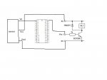
I'd like to switch relay on/of using Sharp IR proximity sensor GP2D120XJ00F ( 3 wires:Vcc,GND, Vo) and PIC 16F886 chip.
Both sensor and relay are powered by 5V, relay current is 27mA.
Sensor's output varies between 0.2V-2.9V.
Are any resistor needed on PIC's input /output? Can I connect relay directly to PIC's output?
Would anyone be able to provide a simple circuit, I'm not sure how to make connections.
and a code to switch relay on for 2sec. when there is reflection detected by sensor.

Any help much appreciated
 

inglewoodpete

Senior Member
Welcome to the PICAXE forum.

The PICAXE 28X1 is based on the PIC16F886 chip. You will have to confirm that you actually have a 28X1 before we can help you here. If you are using a 'raw' PIC16F886 then you'll need to get help from Microchip's PIC forum.
 

SAborn

Senior Member
What do you want to do with the sensor as it only has a range of about 30 cm (1 foot) and at that distance the sensor output voltage will be around 0.3v which is too low to trigger a input on a digital pin, it might work with ADC, but there is not a lot of difference between 0v and 0.3v to detect a input from.
At 4cm it will have an output of about 3.0v which is fine to work with, so you need to tell use how you want to use the sensor.

Have you read the data sheet
https://www.sparkfun.com/datasheets/Sensors/Infrared/GP2D120XJ00F_SS.pdf

Yes you can connect the sensor output direct to a Picaxe input as the sensor voltage is below the 5 volt max allowed for a Picaxe input.
 

sanok

New Member
This must be 28X1 because it works with Picaxe logicator. Chip is on a circuit board which was build by my son at school and it was used for some simple robot.
 

sanok

New Member
SAborn,
I'm making a cat deterrent to stop cat entering certain area. When cat passes within the sensor's working distance ( not more than 30cm from sensor) the relay will switch on the 240V solenoid valve and bloody cat will be sprayed with water.
Thees sensors are widely used in obstacle avoidance robots powered by picaxe or arduino. I've watched many videos of them and it seems that sensor is activating microcontroller at the max distance (30cm) and not just at few cm. Are you sure that 0.3 V wont trigger input?
Yes you can connect the sensor output direct to a Picaxe input as the sensor voltage is below the 5 volt max allowed for a Picaxe input.
I was asking if the relay can be connected directly to the output if relay's current is 27mA ?
thanks
 

SAborn

Senior Member
The picaxe has a safe output current per pin of 20mA so 27mA is a little high for a picaxe, although a simple transistor between picaxe and relay will easy fix the problem, or you could use a solid state relay and drive it directly off the picaxe pin.

Are you sure that 0.3 V wont trigger input?
Most picaxe chips have a Schmitt trigger input (some have TTL ) and require a voltage above or below half the supply voltage before they detect a pin change.
Using ADC means it will read the voltage on the pin and give a decimal value between 0 and 255 using readadc for 0-5 volts, as 0.3v is very close to zero volts it will be hard to detect a precise change and not get errors.

Then adc requires a little more code and testing to get it sorted, although it should be do able.

Any effort is worth it to stop cats causing problems ........ even Click...Bang! (no picaxe required)
 

SAborn

Senior Member
Should not know what a solid state relay is its one of these.

http://www.ebay.com.au/itm/280776557335?ssPageName=STRK:MEWAX:IT&_trksid=p3984.m1438.l2649#ht_4202wt_1170

I would suggest you use a garden irrigation solenoid and not a 240v one, as the irrigation solenoids work on low voltage normally 24 volts which makes it safer and easier to wire the solenoid to a existing garden tap.

As for your IR sensor, you might consider using one of these.......

http://www.ebay.com.au/itm/Mini-Portable-IR-Pyroelectric-Infrared-PIR-Motion-Body-Sensor-Detector-Module-/300956157508?pt=AU_B_I_Electrical_Test_Equipment&hash=item4612628644

I dont know if a cat will trigger it, and i dont have a cat to test it out on, but it would allow a bigger scope of use if out fury friend triggered the sensor.
The sharp IR sensor might give problems with dust and crud on the sensor lense and has limited range with reading problems at close to full distance range.
 

sanok

New Member
First I will try to make it work with the hardware I already have. Can change the distance between cat and sensor by making the passage narrower
to get higher output voltage.
So what would the code look like to trigger relay when sensor detects reflection, and turn it off when no reflection?
thanks
 

Dippy

Moderator
Can you post a (proposed) schematic (electrical circuit diagram)..
With the sensor O/P being 2.5V ish that would be safe but many would advise a series resistor just to be safe (330R to 1k is fine).
I haven't looked at sensor Data Sheet to see if there any other complications, that needs doing first.
I'd connect sensor to DMM first to see what the likely return signal is before connecting to PICAXE.


The basics (haha) will involve ReadADC/ReadADC10 (to read the output from your sensor.
Then use an IF statement to compare the returned value (from ReadADC) with a 'threshold' value.
IF X > Threshold then ...
(Manual 2)

You can improve your code once you have got the fundamentals working.

And you can see how to switch a relay in the PICAXE Manuals. (Manual 3 page 14).
And simply set a pin High or Low to switch relay on and off.
 
Last edited by a moderator:

sanok

New Member
I'd connect sensor to DMM first to see what the likely return signal is
Sensor output is between 0.3-3V. I've read in some manual that the analogue input voltage range can be the PICAXE power supply range.

Below is approximate schematic without power supply (to not complicate), it will be powered by 5V.
Basically sensor output to one of picaxe inputs and transistor's base to one of outputs (not sure which one)
What are the voltages on picaxe output pins? As I'll be using different transistor and need calculate resistor value.

schematic.jpg
 
Last edited:

Dippy

Moderator
Re: Technical editing my last post and deleting SABorn's....
I can, on this occasion, honestly say that I hadn't noticed the double-meaning.
You and Technical have dirty minds. And amazing how a rude word that rhymes with "mugger" is allowed. ;)

Sanok's link doesn't work for me.
Yes, you sensor voltage sounds fine for PICAXE at 5V as you say.

And my suggestion for code ideas to look into hasn't been commented upon.
Does it make any sense to you after looking at Manual 2?
Is the OP expecting the code written in full?
 

sanok

New Member
The link is now OK.
The manual is not very clear for me, I wouldn't know how to write in a correct syntax. I would need a one for Dummies as I'm totally green with coding.

Can you provide a template and I will enter pins and other parameters according to connections
thanks
 

SAborn

Senior Member
Yes sorry Dippy and Technical for my comment, i did try to keep it clean, i had found a little humor in your wording ;), perhaps i just have a twisted view on such things :confused:.

The link is broken for me too.

All up my view is its a poor sensor for the application and will be hard to code for good results, but it can be made to work if you have enough skills with some trial and error testing.
At the end of the day all that needs to be achieved is a wet cat.
 
Last edited by a moderator:

sanok

New Member
Little study and I got it working with this:

main:
readadc 0,b1
if b1 > 50 then bang
goto main
bang:
high 7
pause 1000
low 7
goto main
SAborn you right, a lot of trial and testing. Best value at which picaxe is triggered is 50,
anything below and it comes on at random, and above 50 distance to sensor reduces too much
 

SAborn

Senior Member
You could use "Readadc10" that will return a value between 0 and 1027 (readadc = 0 to 255) and it might allow for a little finer control with your setting.

Good to see you managed to get it working.

One tip you can try is to use "debug" to actually view the ADC reading as you play with the sensor, then you will see at what value you need to use in your code for a trip point.

Try...

main:
readadc10 0,w0
debug
pause 300
goto main


Note this is using readadc10 so the value will be a word and displayed in W0 (b0 + b1) and you might need to click the arrow [>>] to display the word variables on the debug screen.
 
Last edited:

sanok

New Member
With readadc10 values below 150 trigger output by itself without swiping hand over the sensor, at 200 it is stable but distance is only 15cm.
I wonder how those obstacle avoidance robots work with this same type of sensor, they seem to navigate smoothly and react at 30cm from obstacle.
Is there a different command than "If...Then" to achieve the same result?
 

SAborn

Senior Member
I did tell you it would not be easy, as at 30cm you are trying to read about 0.3 volts (not very much) and at 15cm you would have about 1-1.5 volts.

You could try taking several readings and add them together, that might help to stabilize the average reading and remover some fluctuations.

Try this test with 10 readings, the total value of the 10 readings are in W1.

Code:
Main:

	for b5 = 0 to 9
	readadc10 0, w0
	w1 = w1 + w0
	next b5	
	debug 
	
	w1 = 0
	pause 300
	goto main
 

sanok

New Member
Debug screen shows W0 values between 70-500 and W1 shows 10 times higher than W0,

A sonar or motion sensor will be the best solution, as my sensor is totally wrong for this application.
But out of curiosity and to learn something, how to modify my code to take several readings before trigger (if that can be done)
or to use test data in my code?

thanks
 

SAborn

Senior Member
how to modify my code to take several readings before trigger (if that can be done)
or to use test data in my code?
Im not sure what you are asking but here is several readings in your code and debug, you will need to remove the comment ( ' ) before debug if you want to show the data on screen.
debug will mess with your timing a little and the pause wont be correct as debug slows the program a little, so remove debug in any final working program.

Code:
main:
	
	for b5 = 0 to 9
	readadc10 0, w0
	w1 = w1 + w0
	next b5
	
	'debug
	
	if w1 > 750 then bang
	goto main
	
bang:
	high 7
	pause 1000
	low 7
	goto main
 
Top