Considerations for Picaxe running 24/7?

Shafto

Senior Member
I'm making a little LED display with a 28X2 chip that will be on all the time.

18 separate outputs from the 28X2 will turn on an N-channel MOSFET which will supply power to each of the 18 LEDs in a sequence, and a pot to adjust the pause time between switching to the next output. The current through the MOSFETs will be about 400mA, and the sequence will switch at about 1hz.

I have a UL listed 5V "wall wart" to supply power to the Picaxe, and another UL listed 12V supply that will power the LEDs through the MOSFETs.

Since this is something that will be plugged into mains and always on, what considerations need to be made to ensure everything will work properly and safely?

I will be putting a fuse on each of the 18 outputs, as well as the 5V input and 12V input.

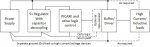
Should I use opto-isolators between the Picaxe outputs and the MOSFETs, so that I don't have to connect the 0V side of both the 5V and 12V transformer together, or is that not necessary?

Is there anything else to consider? Is it possible for the Picaxe to freeze or crash when on for such a long time? Maybe an external 555 timer to reset the Picaxe every 24 hours or so?

I'm going to get working on the schematic and post it here when I'm done, but am curious of a few things before I start.
 

hippy

Technical Support
Staff member
Electrical safety shouldn't be a problem if using external power supplies but a fuse on the inputs won't do any harm. Having fuses on each of the outputs and using opto-couplers to connect to the MOSFETs seems like overkill to me.

I would suggest, rather than separate 12V and 5V supplies, derive the 5V from the 12V using a regulator internally, then you just have one supply. Having the 12V and 5V 0V's connected together shouldn't be a problem.
 

bpowell

Senior Member
I've got a pair of PICAXE (sender and receiver) that have been running for over 4 years now...no freeze-ups...they continue to work as expected.
 

inglewoodpete

Senior Member
I have built three different high-powered LED lighting systems (200w, 450w & 460w) driven by PICAXEs running 24-hours a day. The lights only run during certain hours but the PICAXEs run constantly, doubling as a crude 24-hour clock synchronised by the sun.

Care must be taken with the wiring to ensure that the high current and low current supplies are kept separate, especially the 0v return paths. If wired incorrectly, electrical noise in the high-current 0v returns can cause the PICAXE (or any other microcontroller) to reset.

Two use PWM-driven P-channel MOSFETs, without opto-isolators, although there are buffer transistors for the MOSFETs. The third (200w) one uses a commercial DMX lighting driver controlled by an 08M2. I have not had any problems apart from being blinded by the amount of light that the 10w LEDs radiate :).
 
Last edited:

neiltechspec

Senior Member
I have at least five PICAXE's, one in a 'hostile' automotive environment, that have been running for over two years without a 'lockup/freeze'.
 

srnet

Senior Member
Is there anything else to consider? Is it possible for the Picaxe to freeze or crash when on for such a long time? Maybe an external 555 timer to reset the Picaxe every 24 hours or so?
Of all the common microcontroller platforms, including the very popular and 'ard' to program one, if reliabilty is key, the PICAXE is a clear leader.

I dont recall a single instance of a PICAXE 'crashing' and I did spend a couple of years developing and testing just one application.

What is refreshing about your post is that you are thinking about and planning for what happens when your setup does not work as intended, not many people do this even though it must be obvious that microcontrollers\computers do fail.

An external watchdog device independant of the PICAXE that can reset the PICAXE if it program stops its normal operation, is in my view essential.
 

Shafto

Senior Member
Thanks for the input everyone.

inglewoodpete, I don't know how to wire it "properly" to avoid issues of a noisy ground if it's shared by the 5V supply for the pixaxe and the 12V supply for the LEDs. I know what needs to go where to make it happen in a perfect world without noise, but I don't have the intrinsic understanding of how to avoid electrical noise.

Since I'm using N-channel the switching will all be done on the 0V, hence my idea to not cause any problems I don't know how to fix and just keep the 5V and 12V completely isolated with optos driving the MOSFETs. Overkill if you know how to do it properly without, but unfortunately I'm not there yet, so I suppose I should just play it safe, unless someone can really boost my confidence about dealing with noise on the shared 0V.

I've had noisy ground issues in other projects I've done, where switching power caused ADC input fluctuations. I found that making an RC filter with the 0.1uF cap on the Picaxe supply and something like a 10ohm resistor into the +V, the issues went away, but beyond that little discovery I made, I really have no idea how to deal with electrical noise.
 

inglewoodpete

Senior Member
inglewoodpete, I don't know how to wire it "properly" to avoid issues of a noisy ground if it's shared by the 5V supply for the pixaxe and the 12V supply for the LEDs. I know what needs to go where to make it happen in a perfect world without noise, but I don't have the intrinsic understanding of how to avoid electrical noise.
Here is a drawing that I made a few years ago to explain keeping high ground currents away from the microcontroller.
Logic Earth2.jpg
There may be some benefit in providing separate power supply feeds to the 5v regulator and high-current load (where the same power source is being used) but the capacitors on the 5v regulator circuit usually isolate sufficient noise.
 

techElder

Well-known member
The reason to separate the high current ground wire is because it is actually a resistor. Copper has resistance, too!

If there's only a little current through a wire, then (via Ohm's Law) there is only a little voltage produced from one end of the wire to the other end of the wire. The capacitors in the 5 volt regulator can filter out small changes easily.

However, when you have large, pulsed currents from motor drivers etc. through a wire, there is also (via Ohm's Law) large, pulsed voltages produced from one end of the wire to the other end of the wire. You could place very large capacitors in the 5 volt regulator to filter these large changes in input voltages, but it is much better to wire the circuits so those high currents don't flow in the same circuits that the 5 volt regulator uses.

That's what IWP shows in his diagram. Follow the current path in the high current section, and you will see that the two circuits are separated.

Remember, we're speaking of the physical wiring; not just lines drawn on paper.
 
Top