Connect temp sensor to axe002

jeppfi

New Member
I buyed a DS18B20 and a PICAXE 18x.
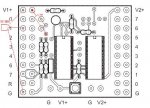
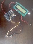
I have connected the wire to the chip (The same chip as the LCD).

I have connected the two power wires to the 4,5v batteybox.
I found a script that writes the temperature every 15. sec. But it only shows 0,0,0,0.
Is it the power, the script or the connection wire?

The script:
Code:
for b0= 0 to 255			'begin 256 data readings @ time set by WAIT/SLEEP
pulsout 2,500				'brief flash from pin 2 LED indicates datalogging
readtemp 1,b1				'direct Celsius reading of DS18B20 temp. returned 
serout 2,n2400,(#b1,44)			'Now allows display of data as gathered too !
write b0,b1 				'sequentially write values to EEPROM locations
wait 15 				'Checks every 15 secs (max 65)-alter to suit etc	
next b0					'Gathering automatically stops after 256 samples
 
Last edited:

inglewoodpete

Senior Member
The code looks OK.

Check the connections to the DS18B20. Input pin 1 is leg 18 on an 18X. Also check that you have the 4.7k ohm resistor to +5v - the circuit uses an open-collector output so, without it, you will see all zeroes.
 

jeppfi

New Member
I have connected the wire on the right side of the chip.
What is an open-collector?
I have connected the GND to the 0V and the VDD to the V+ on the PICAXE pwr holes.
Is that correct?

Also check that you have the 4.7k ohm resistor to +5v - the circuit uses an open-collector output so
What do you mean with this?:p
 
Last edited:

Peter M

Senior Member
well spotted IWP

it means as well as conecting the output of the sensor to the input of the picaxe it also needs a 4k7 resistor connected to +5v
Code:
    5v
    |_____
    |     \
    |     / 4k7
    |     \
    |     /      |
tempD-----o------| picaxe
    |            |
    |
    |
    0v
 
Last edited:

inglewoodpete

Senior Member
I'm suffering with a slow dial-up connection at the moment.

Basically, no. The resistor must be used.

'Open collector' is where the output pin of the chip is the Collector of an NPN transistor. The emitter of this transistor is connected to 0v. When this output transistor is turned on, the output (Ie collector) is pulled low, towards 0v. When the transistor is turned off, the collector is high impedance, effectively open circuit.

The 4.7k ohm resistor is use to pull the output line high (towards +5v), giving the 2 output states of 0v and +5v. Without the pullup resistor, the output would be indeterminate, tending to remain at 0v.

An open collector configuration behaves like a switch between the output pin and 0v.
 

hippy

Technical Support
Staff member
Also see the example of connecting the DS18B20 given on page 128 of "PICAXE Manual 2 - Basic Commands"
 

jeppfi

New Member
Must i connect the power to the chip V+ and 0V, or to the same powersupply as the PICAXE?

Somebody that can draw a sheet how to connect the temperature sensor?
 
Last edited:

hippy

Technical Support
Staff member
Hint

Must i connect the power to the chip V+ and 0V, or to the same powersupply as the PICAXE?

Somebody that can draw a sheet how to connect the temperature sensor?
Please see the example of connecting the DS18B20 given on page 128 of "PICAXE Manual 2 - Basic Commands"
 

jeppfi

New Member
I don't see a example there :S

Edit: Isin't it a 4,7 resistor on the project board?
 
Last edited:

inglewoodpete

Senior Member
I think you need to clarify exactly which PICAXE module you have.

Is it the CHI030? If you have the Programming Editor Loaded on your PC, refer to document C:\Program Files\Programming Editor\datasheets\CHI030.pdf, it describes different 18-pin project boards.
 

jeppfi

New Member
I think you need to clarify exactly which PICAXE module you have.

Is it the CHI030? If you have the Programming Editor Loaded on your PC, refer to document C:\Program Files\Programming Editor\datasheets\CHI030.pdf, it describes different 18-pin project boards.
yes, it is the CHI030, somebody that can draw a simple chart so that I can see how I must connect the DS18B20 to the project board. I have a 4k7 resistor
 

inglewoodpete

Senior Member
OK. Now we're getting somewhere. Have a look at the CHI030 circuit diagram (page 7 of the CHI030 document) and the diagram of the board (page 1)

Assuming you are using Input 1 (leg 18 on the physical chip), ensure that R7 is NOT installed on the board. (It is not included on my version of the CHI030 board that I purchased about a year ago). R7 would pull Input 1 low, which is not what we want.

You need to connect your 4.7k resistor between the left-most hole provided for R7 and V1+ (either of the 2 solder pads at the very top of the left-hand side of the board). It may look a little untidy - this board was not really designed for the DS18B20.

Ensure the DS18B20 is connected as described in the diagram on page 128 of Manual 2 (commands) - The ReadTemp command page.

I hope this help you to get your project working. I need some sleep - it's 1:00am. Please let us know how it goes.
 

Attachments

Last edited:

jeppfi

New Member
The LCD still show just zero :(

Code:
readtemp 1,b1 ‘ read value into b1
serout 5,N2400,("Temperature:",#b1) ‘ transmit value to serial LCD
 
Last edited:

inglewoodpete

Senior Member
Make sure the +5v and 0v leads are the correct way around on the DS18B20. Check the colour bands on the resistor: Yellow/Violet/Red + Gold for 5% tolerance (or Yellow/Violet/Black/Brown + Brown for 1% tolerance).

I've run out of ideas. Without actually seeing your heardware wiring, I can't help much further. One option is to take a photograph of the wiring and post it on the forum.
 

jeppfi

New Member
Make sure the +5v and 0v leads are the correct way around on the DS18B20. Check the colour bands on the resistor: Yellow/Violet/Red + Gold for 5% tolerance (or Yellow/Violet/Black/Brown + Brown for 1% tolerance).

I've run out of ideas. Without actually seeing your heardware wiring, I can't help much further. One option is to take a photograph of the wiring and post it on the forum.

Heres your picture :)

Sorry for the bad quality, my HTC S710 has a bad camera :p
 

Attachments

inglewoodpete

Senior Member
The photo is a bit blurry. It looks like to 'curved' side of the DS18B20 is upwards (visible) - that's good.

More questions (always questions);)

What power source are you using to power the board?

Do you have a multimeter? If so, what is the voltage reading across the 18X (legs 5 and 14)?

Can you confirm that the resistor you added has the correct coloured bands?

-Peter
 

jeppfi

New Member
I'm using 3xAA batteries, 4,5v. the colors are correct. I have a 6v battery that I use to power the serial LCD screen, is that to much? I also have a 12v battery.
 

inglewoodpete

Senior Member
Are you able to read the voltage across legs 5 & 14?

Try the following program:

Code:
MainLoop: ReadTemp 1, b1
              Debug
              Wait 3
              GoTo MainLoop
If that gives no data, I suspect the DS18B20 may have been damaged (Heat from soldering?)
 

hippy

Technical Support
Staff member
The DS18B20 is rated for an absolute maximum power supply of 5V5, so 6V will be too much. Don't do it.

I've always been in two minds about the usefulness of the CHI030 type of project board /starter kit for people who are new to PICAXE and electronics and want to start experimenting. Having to hack something into being something else is no easy task for the more advanced let alone the beginner and there is plenty of scope for things to go wrong and not work.

Much simpler boards which contain just a PICAXE, download circuit, resonators and reset buttons would I belive be much more useful. My preferences would be AXE021 for the 08's, AXE022 for the 28/40's, and AXE090 for the 08/18/28's.

http://194.201.138.187/epages/Store.storefront/?ObjectPath=/Shops/Store.TechSupplies/Products/AXE021
http://194.201.138.187/epages/Store.storefront/?ObjectPath=/Shops/Store.TechSupplies/Products/AXE022P
http://194.201.138.187/epages/Store.storefront/?ObjectPath=/Shops/Store.TechSupplies/Products/AXE090

Cheap, no nonsense, equivalents of AXE021 for the 18, 28 and 40's would be a nice addition to see.

Failing that, breadboard is IMO the best option.
 
Top