Thanks!
On each motor there is a quadrature encoder, which pulses is read by the picaxes. Without the pulses, the program won`t do much.
This is a controller for a home theater screen masking system. It`s been about a year since I built it. I also built a small version of the mechanical system that I used during programming. The motors and encoders are the same as will be used later on the full size system. I had to deal with a radon-problem in my theater-room, so the masking system has not yet been installed. And, of course I need to make it work properly.. I don`t have a complete schematic, but I post the circuit layout, in case you have the time to have a look
")
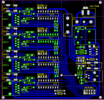
There are two boards, the controller board has 4 18M2s. The circuits are the same for all 4. The encoder-pulses enter at the ENC1 - ENC4 connectors at the left. The Q1 to Q4 are just switches to turn off power to the encoders, to save some LED-life when the motors are not moving. The IR-signal is connected to pin 12 on all 4 18M2s. The right hand side is the power-supply (there is a 100uF in parallel to C6 not shown), a trigger-circuit that will turn on the controller when the projector is turned on, the connector for the IR-chip, and a output connector for connection to the relay-board.
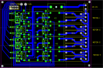
IC-1 on the controller-board control the Q1 and Q2 relay-driver transistors on the relay board. Q1 will turn on or off the 220V voltage out of relay K1 (pin 5). Q2 select which of pin 4 or 5 on relay K2 will have 220V, turning the motor-1 CW or CCW. The RC-1 to RC-8 are RC-snubbers.
Comments are welcome
I`ll post some code later. I used a lookup-table that you suggested a year or to back for decoding the quadrature pulses
Controller board:
Relay-board: