Compact PWM PV Charge Controller using 08M2

Solar Mike

New Member
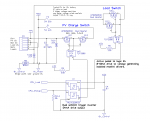
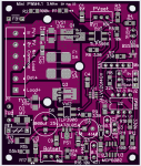
Here is a basic design for a PWM type PV solar charge controller, using a Picaxe 08M2. Ideal for smaller 30W panels charging a 10AH or so lead acid battery.
I have a number of projects coming up that require small panels hooked up to various size 12 volt gel or Lifepo4 batteries, in stand alone field operations powering pumps, control valves etc. After playing with various designs for small MPPT controllers, MPPT is really over-kill for small setups, so am switching to simple PWM only.,
Sorry about smd components used here, everything I build now uses smd components.

Having many small dual logic level mosfets (30v @80amps 5.2mR) left over from a Lifepo4 BMS project, decided to use them in this design; the PV charger part is 2 back to back devices (single package) driven by a current to voltage isolated mosfet driver, these drivers originally designed for use in SSR's have on\off times approx 1mSec so the PWM frequency must be quite low, quite ok for a battery charger.

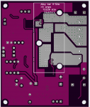
The high side load switch has two in parallel to bring the series resistance down, this switch gets turned off should the battery volts get too low.

A novel part of this circuit is the load switch is driven from the C.3 input only pin, by programmably setting the C.3 pull-up on, the output voltage divider feeding the schmitt trigger inverter gate is set high; and low when the pull-up is disabled.

Schematic below:

25883

25884

25885

25886


Cheers
Mike
 
PCB 72x60mm:
25888
25889

Gerber files Attached.

I am waiting for the pcb's to come back, will then test it and write some software, post back here later.

Cheers
Mike
 

Attachments

I'd checked in yesterday to see if you had the boards back so my guess on production & shipping seems to have been close.

Like the cat who ate cheese and lay by the mousehole, I'm waiting with bated breath ;-)
 
Finally have some software, attached as zip file. Code is well commented, so I won't elaborate further here.

Have given the code and the board a good test, all works as expected, no changes required to pcb layout.
For the 12v gel battery I was using and the 30watt PV panel, resistors R1 = 20k, R2 = 100k, R15 = 47k, R17 = 2k7.

The software has a calibration mode for setting the Battery and PV voltage sense pots.
Charge and load currents up to 5 amps, no additional heat sinking is required; if currents are higher from a larger panel then place a piece of silpad material under the pcb and bolt to an alloy plate.

Cheers
Mike
 

Attachments

Beautiful and well executed project. (y)
I really like the fact that you have included the component's value in the silkscreen.
I quickly browsed your code. Will ask questions later if I have any doubts.

PD: it is amazing the capabilities of those SMT Mosfets.
 
I have also created an alternative variant of this low power PWM controller using a PICAXE 14M2, it used shunt PWM regulation and will have lower standby power when not under charge, which maybe more important for smaller batteries; also has extra leds showing charge status.

Look over on The Backshed

Cheers
Mike
 
Hi,
As I understand the circuit, the solar panels see a constant load provided by capacitor c2. Power from this capacitor passes to the load switch mosfets in pulses. The period of the pulses depends on the voltage of the panels. I'm guessing around 1ms. From the AP90N03GD datasheet, figure 11, safe operating area, does this mean that the maximum current through the device at 20V is near 100A? Thanks.
 
C2 0.1uf ceramic, is there for noise or spike suppression only. Max current is determind by the current limited PV spec of the panel employed.

The two mosfets are always turned on, no switching, until the battery voltage rises to a defined set point; then they are turned off, only turned back on when the battery voltage drops below the set point. Set points being Bulk, CV or float, the period of the switching varies according to any external load on the battery. 10s of Hz, the isolated mosfet voltage driver used here is a low frequency device, switching times are approx 2mSec, there is no high current spike.

Mike
 
Thanks Mike.
So if the AP90N03GD charge switch mosfets are effectively passing DC, does this mean that the maximum current, according to figure 11 on the datasheet, is 5A at 20V or 10A for the two of them?
If the charge mosfets pass DC, especially during the bulk charge state, what keeps the PV panels near maximum power point?
Brendan
You are not interpreting the data sheet correctly, the SOA curve should be looked at where the switching time is approx 1mS, not DC, at the 1mS point and say 20v panel the current can be many tens of amps, once the device has turned on the voltage drop across it is mVolts only, so the current capability is much higher. We are only talking small PV panels here, 100w or so, the devices hardly get warm.
If the mosfets were turned on much quicker eg 150 nS which you would get from a high current gate driver chip, then the more power the device could switch.

A PWM charger does not have a mppt operation, it puts pulses of current at the panels rated output into the battery once a set point has been reached. When switched continuously on, the PV voltage is dragged down to the battery volts, no mppt, so its not as efficient, but for small systems this hardly matters.

Mike
 
I think I get it. The datasheet for the TLP3906, section 11 has the turn-on and turn-off times at 1ms. The SOA curve is only applicable to the time that the device switches. I have a rescued a couple of IHW25N120R2, IGBTs out of an induction cooker and couldn't understand why they worked given my interpretation of SOA graphs. Thanks again.
 
Back
Top