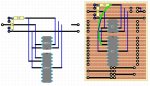
I don't have the money for a Picaxe protoboard so I soldered this together myself. It has room for an 08M2+ and 18M2. They share the download socket. It is missing the switch by the battery connectors, so you cannot yet individually turn off/on each Pic.
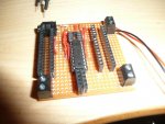
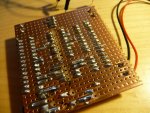
The goal was to use it with a breadboard, so it has those female headers on each side, for connecting jumper wires. The screw terminals on the buttom are connected to their jumpers in case you need to connected something that cannot sit on a breadboard. The upper terminals are for the power in case you want the Pics to run off something other than a battery pack.
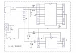
It programs both kinds of Pic fine, as long as only one is in the socket. I hope the power switch will solve this. The 08M2+ is not connected to power yet so I connect a jumper from the larger chip to the smaller one's power header.
How about instead of powering on the one to program, I do something with turning on/off the 0v connection to the download socket?
I was wondering how you could make both pics send some data through the same socket to the terminal in the PE. I was thinking of doing something with connecting them together and having one chip tell the other when to send:
The back off part is so they do not start sending at exactly the same time. The pins B.1 and B.0 would be connected together from one Pic to the other,so they can tell eachother whether to send or not.
EDIT: I got the 16-seg LED chaser to work and I will post a video soon.
The goal was to use it with a breadboard, so it has those female headers on each side, for connecting jumper wires. The screw terminals on the buttom are connected to their jumpers in case you need to connected something that cannot sit on a breadboard. The upper terminals are for the power in case you want the Pics to run off something other than a battery pack.
It programs both kinds of Pic fine, as long as only one is in the socket. I hope the power switch will solve this. The 08M2+ is not connected to power yet so I connect a jumper from the larger chip to the smaller one's power header.
How about instead of powering on the one to program, I do something with turning on/off the 0v connection to the download socket?
I was wondering how you could make both pics send some data through the same socket to the terminal in the PE. I was thinking of doing something with connecting them together and having one chip tell the other when to send:
Code:
backoff:
random w2
let w1 = w2 // 500
pause w1

main:
let dirsB =%11111101
if pinB.1 = 1 then main
if pinB.1 = 0 then send

send:
let pinsB =%00000001
sertxd ("Data =  ", #w0,13,10)
pause 100
let pinsB =%00000000
goto mainEDIT: I got the 16-seg LED chaser to work and I will post a video soon.
")