mrburnette
Senior Member
Update:
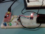
I found that I needed 3 general purpose silicon diodes such as 1N4148, etc. (cathode toward the PICAXE pins which are pulled Low) to properly reduce leakage current with my tri-colored LED. This is especially important for the Blue LED as it shares the pin with the junction of the thermistor and 10K for ADC use.
I my blog of the same title Cold-Hearted-Orb-That-Rules-The-Night, I described how I ran across an unusual pool toy at the local WalMart. With the translucent orb disassembled and my imagination satisfied, I began to give some thought on investment recovery of my $2.50 ... do something unusual with colored LEDs.
The blog covers my thinking processes. But, I still needed to write some PICAXE BASIC to ensure that the idea was reasonable and that a minimum of parts and a Nichia tri-colored LED (common anode... a single 220 Ohm resistor is used for current-limiting) could be used. The code below is my POC code and tracks a digital temperature sensor degreeF by degreeF. Internal to the code, Celsius is the root temperature, so this can easily be changed, however, I personally find Celsius temps without the decimal point a wee too broad for my tastes.
Blinking LED Color Scheme:
Case 50 to 59 ' Blue LED ; C.4
Case 60 to 69 ' Green LED ; C.2
Case 70 to 79 ' Red LED ; C.1
Please note that I have given Peter Anderson credit for the temperature routines, although I have taken some poetic license with his code... if there are errors, it is my fault and not the Prof's.
Please note that I am using Magic Morse "encoder" algorithm for generating the DIT / DAH Morse code flashes for the digit_F temperature. This algorithm is published and explained elsewhere on this Forum and in my blogs.
When implementing the above, you will need a 5.00V power source for the PICAXE or you will need to modify the routine if a lower voltage reference is provided to the ADC10 in the PICAXE 08M2+.
- Ray
I found that I needed 3 general purpose silicon diodes such as 1N4148, etc. (cathode toward the PICAXE pins which are pulled Low) to properly reduce leakage current with my tri-colored LED. This is especially important for the Blue LED as it shares the pin with the junction of the thermistor and 10K for ADC use.
I my blog of the same title Cold-Hearted-Orb-That-Rules-The-Night, I described how I ran across an unusual pool toy at the local WalMart. With the translucent orb disassembled and my imagination satisfied, I began to give some thought on investment recovery of my $2.50 ... do something unusual with colored LEDs.
The blog covers my thinking processes. But, I still needed to write some PICAXE BASIC to ensure that the idea was reasonable and that a minimum of parts and a Nichia tri-colored LED (common anode... a single 220 Ohm resistor is used for current-limiting) could be used. The code below is my POC code and tracks a digital temperature sensor degreeF by degreeF. Internal to the code, Celsius is the root temperature, so this can easily be changed, however, I personally find Celsius temps without the decimal point a wee too broad for my tastes.
Blinking LED Color Scheme:
Case 50 to 59 ' Blue LED ; C.4
Case 60 to 69 ' Green LED ; C.2
Case 70 to 79 ' Red LED ; C.1
Please note that I have given Peter Anderson credit for the temperature routines, although I have taken some poetic license with his code... if there are errors, it is my fault and not the Prof's.
Please note that I am using Magic Morse "encoder" algorithm for generating the DIT / DAH Morse code flashes for the digit_F temperature. This algorithm is published and explained elsewhere on this Forum and in my blogs.
Code:
' MorseTemp_08M2.bas - PICAXE-08M2+ by M. Ray Burnette
' 428 Bytes / 2048
' Public Domain Software - portions are copyrighted (c) as indicated in comments
'
' NTC thermistor + 10K resistor for temperature measurement and
' a Nichia Corp NSTM515AS RGB LED - common Anode for blinking temp as Morse Code
' Temperature LED color bands:
'	RED:		70 - 79 F
'	GREEN:	60 - 69 F
'	BLUE:		50 - 59 F
'
' Measures voltage across the thermistor and uses a combination of table lookup
' and linear interpolation to calculate the temperature in degrees C.
'
' NTC is grounded on one side and 10K is used as a pull-up to +5.
' ADC is at junction, (physical) PIN #3 on PICAXE 08M2
'

#picaxe 08m2
{
#Terminal 4800
#freq m4	' The default power-up operating frequency is 4MHz

  Symbol ADVal     = W0
  Symbol TC_100    = W0	; ADVal not needed when TC_100 is calculated
  Symbol ADValHi8  = B2
  Symbol ADValLow2 = B3
  Symbol N         = B4
  Symbol Diff      = B5
  Symbol Whole     = B6
  Symbol F_Temp 	 = B6
  Symbol Magic     = B7
  Symbol PIN	 = B8
  Symbol SignFlag  = B4	; N    is not needed when this is used
  Symbol Digit     = B5	; Diff is not needed when this is used
  Symbol Channel	 = 4			; 08M2 Physical PIN#3, Port C.4
  Symbol RED	 = 1	; C.1
  Symbol GREEN	 = 2	; C.2
  Symbol BLUE	 = 4	; C.4

  ; Initialize temporary variables for Magic Morse
  B11 = " "	: B12 = " "	: B13 = " "	: B14 = " "	: B15 = " "

  ; Physical connections for Nichia Corp NSTM515AS RGB LED - common Anode
  ; 220 Ohm resistor Vdd (+5V) to common Anode
  ; RED   lead to C.1 physical pin #6
  ; GREEN lead to C.2 physical pin #5
  ; BLUE  lead to C.4 physical pin #3

  ; Optional statement for 08M2+ ADC
  LET ADCsetup = %0000000000010000	; Channel 4 == C.4 / Page33, Man#2

  ; We have no need for I/O with the console, so disconnect listener
  PAUSE 4000
  DISCONNECT
}

  Do
{
	GoSub MeasTemp

	If TC_100 != $7fff Then
		GoSub DisplayTemp
	Endif

	nap 10 ' Sleep in low power mode 16 seconds
  Loop
}

MeasTemp:
	; Based upon routines copyright by P.H. Anderson
	; http://www.phanderson.com/picaxe/picaxe_thermistor.html
{
	ReadADC10 Channel, ADVal

	ADValHi8  = ADVal / 4    ' isolate the high 8 bits
	ADValLow2 = ADVal & $03 ' low two bits

	; Adjust the default 10512 value if other ADC reference voltages are used
	; Also adjust the value to provide correct measurement with specific
	; Thermistor and resistor combinations
  	TC_100 = 10550 ' ADJUST AS REQUIRED

   	; In this program, there is no console I/O so errors are not displayed
	If ADValHi8 < 16 OR ADValHi8 > 251 Then	' Out of Range
		TC_100 = $7fff
	End If

  	For N = 0 to ADValHi8 ' continue to subtract
     		Read N, Diff
     		TC_100 = TC_100 - Diff
  	Next

  	' Now for the low two bits, a linear interpolation
  	N = N + 1
  	Read N, Diff
  	Diff = Diff / 4 * ADValLow2
  	TC_100 = TC_100 - Diff

	Return
}

DisplayTemp:
{

	SignFlag = Tc_100 / 256 / 128
	If SignFlag = 0 Then Positive
	TC_100 = TC_100 ^ $ffff + 1	; twos comp
	; If we were printing results, a Negative Sign would be printed at this time


Positive:
	' C --> F
	TC_100 = TC_100 * 9 / 5 + 3200
	Whole = TC_100 / 100
	Digit = Whole // 10

	; Find the Magic Morse number for the digit temperature
	; Magic Morse algorithm and derivatives (c) 2011 by M. Ray Burnette,
	; M. Ray Burnette is AKA Ray Burne on Instructables and other online forums
	Lookup Digit, (253,245,229,197,133,5,13,29,61,125), Magic

	; Magic Morse algorithm ... in reverse
	; Could just as easy use 0's and 1's or ASCII values
	B11 = " "	: B12 = " "	: B13 = " "	: B14 = " "	: B15 = " "
	; First the DAHs
	If Magic > 128 then : B15 = "-" : Magic = Magic - 129 : ENDIF
	If Magic > 64  then : B14 = "-" : Magic = Magic - 65  : ENDIF
	If Magic > 32  then : B13 = "-" : Magic = Magic - 33  : ENDIF
	If Magic > 16  then : B12 = "-" : Magic = Magic - 17  : ENDIF
	If Magic > 8   then : B11 = "-" : Magic = Magic - 9   : ENDIF
	; Now complete by filling in with DITs
	IF Magic > 0 AND B11 = " " then : B11 = "." : Magic = Magic - 1 : ENDIF
	IF Magic > 0 AND B12 = " " then : B12 = "." : Magic = Magic - 1 : ENDIF
	IF Magic > 0 AND B13 = " " then : B13 = "." : Magic = Magic - 1 : ENDIF
	IF Magic > 0 AND B14 = " " then : B14 = "." : Magic = Magic - 1 : ENDIF
	IF Magic > 0 AND B15 = " " then : B15 = "." : Magic = Magic - 1 : ENDIF

	; Morse Code for last digit is: B11,B12,B13,B14,B15
	sertxd (#Whole," ",B11,B12,B13,B14,B15,CR,LF)


	Select Case F_Temp ; Alias for variable Whole (Fahrenheit)

		Case 40 to 49	' Blue + Green
			' Unimplemented in demo on 08M2 ... so, a trending colder temp
			' will have PIN = 4 and the LED will remain blue... below 50F

		Case 50 to 59	' Blue LED	; C.4
			PIN = 4

		Case 60 to 69	' Green LED	; C.2
			PIN = 2

		Case 70 to 79	' Red LED	; C.1
			PIN = 1

		Case 80 to 90	' Red + Green
			' Unimplemented in demo on 08M2 ... so, a trending hotter temp
			' will have PIN 4 = 1 and the LED will remain red... above 79

		ELSE
  			' Just do nothing...
	End Select


  	; Morse Code for last digit is: B11,B12,B13,B14,B15
	; 250 elements into 60 seconds per minute = 240 milliseconds per element.
	; each dit is one element, each dah is three elements, intra-character spacing is one element,
	; inter-character spacing is three elements and inter-word spacing is seven elements.
	; RED   lead to C.1 physical pin #6
	; GREEN lead to C.2 physical pin #5
	; BLUE  lead to C.4 physical pin #3

	For N = 11 to 15
		bptr = N
		sertxd (@bptr)

		Low PIN			' Turn on (one) of the Nichia's LED elements

 		; Change the Morse Code WPM speed via the three pauses below
		If @bptr = "." Then
			Pause 240		' Dit
		ElseIf @bptr = "-" Then
			Pause 720		' Dah
		EndIF

		High PIN			' Turn off LED
		Pause 240			' Interelement break
	Next N

	sertxd (CR,LF)
	Return
}

 ' EEPROM locations 0 - 15 not used
 ' http://www.phanderson.com/picaxe/picaxe_thermistor.html
{
  EEPROM 16, (254, 236, 220, 206, 194, 183, 173, 164)
  EEPROM 24, (157, 149, 143, 137, 131, 126, 122, 117)
  EEPROM 32, (113, 110, 106, 103, 100, 97, 94, 92)
  EEPROM 40, (89, 87, 85, 83, 81, 79, 77, 76)
  EEPROM 48, (74, 73, 71, 70, 69, 67, 66, 65)
  EEPROM 56, (64, 63, 62, 61, 60, 59, 58, 57)
  EEPROM 64, (57, 56, 55, 54, 54, 53, 52, 52)
  EEPROM 72, (51, 51, 50, 49, 49, 48, 48, 47)
  EEPROM 80, (47, 46, 46, 46, 45, 45, 44, 44)
  EEPROM 88, (44, 43, 43, 43, 42, 42, 42, 41)
  EEPROM 96, (41, 41, 41, 40, 40, 40, 40, 39)
  EEPROM 104, (39, 39, 39, 39, 38, 38, 38, 38)
  EEPROM 112, (38, 38, 37, 37, 37, 37, 37, 37)
  EEPROM 120, (37, 36, 36, 36, 36, 36, 36, 36)
  EEPROM 128, (36, 36, 36, 36, 36, 35, 35, 35)
  EEPROM 136, (35, 35, 35, 35, 35, 35, 35, 35)
  EEPROM 144, (35, 35, 35, 35, 35, 35, 35, 35)
  EEPROM 152, (35, 35, 35, 35, 35, 35, 35, 35)
  EEPROM 160, (36, 36, 36, 36, 36, 36, 36, 36)
  EEPROM 168, (36, 36, 36, 37, 37, 37, 37, 37)
  EEPROM 176, (37, 37, 38, 38, 38, 38, 38, 39)
  EEPROM 184, (39, 39, 39, 39, 40, 40, 40, 41)
  EEPROM 192, (41, 41, 42, 42, 42, 43, 43, 43)
  EEPROM 200, (44, 44, 45, 45, 46, 46, 47, 47)
  EEPROM 208, (48, 48, 49, 50, 50, 51, 52, 53)
  EEPROM 216, (53, 54, 55, 56, 57, 58, 59, 61)
  EEPROM 224, (62, 63, 65, 66, 68, 70, 72, 74)
  EEPROM 232, (76, 78, 81, 84, 87, 90, 94, 98)
  EEPROM 240, (102, 107, 113, 119, 126, 135, 144, 156)
  EEPROM 248, (170, 187, 208, 235)

}- Ray
Last edited: