Code woes
- Thread starter marzan
- Start date
marzan
Senior Member
Hi Paul. I tried that, it didn`t workHi marzan, no you don't need to change the oscillator timing cap. You do have to enable multiplexing by setting a bit in the saa1024's control register. Data sheet page 6.
Paul

Have to check the MX1 and MX2 outputs (a bit hard without a scope tho..)
Marz.
What do you see? 2 digits working ok, the other 2 blank, or all 4 digits on but with unevenly lit segments that don't show the right patterns, or what?
Also have you set the digit banking bits in the control register? There's also a test-all-segments bit in there you could try.
Try swapping the mx connections over: do the other pair of segments work then?
Also have you set the digit banking bits in the control register? There's also a test-all-segments bit in there you could try.
Try swapping the mx connections over: do the other pair of segments work then?
Last edited:
marzan
Senior Member
1 & 3, 2 & 4 showing the same.What do you see? 2 digits working ok, the other 2 blank, or all 4 digits on but with unevenly lit segments that don't show the right patterns, or what?
marzan
Senior Member
I altered the code so as to get the 2 digits showing seconds and tenths of seconds .What do you see? 2 digits working ok, the other 2 blank, or all 4 digits on but with unevenly lit segments that don't show the right patterns, or what?
Also have you set the digit banking bits in the control register?
Try swapping the mx connections over: do the other pair of segments work then?
hippy
Ex-Staff (retired)
Strip back the code to just a test program for the display. I remembered the SAA1064T is what's in a Virgin Media STB so this test program may help. I can't remember what the initialisation bits are but I recall the chip does duplicate digits if not configured right -I altered the code so as to get the 2 digits showing seconds and tenths of seconds .
Code:
HI2cSetup I2cMaster, $70, I2cSlow, I2cByte
Hi2cOut $00, ( %00010111 )
Do
  ...
  Hi2cOut $01, ( b1, b2, b3, b4 )  ' Four digits to display
  Pause 1000
Loop
marzan
Senior Member
I have already tried swapping it out for another one. don`t know whats going on :/ I also did exactly what you said. Just put in values 0,1,2,3 ad got 0,3,0,3So what you're saying is that if you tried to program it to display "1234", you would see "1212"? That does indeed sound like the oscillator isn't running. Have you got a spare saa1064 to try?
Marz.
Hmm... if the oscillator wasn't running, in theory you would only get 2 digits lit.
Strange that you saw 0303. That's digits 1 and 4. They are paired 1 with 3 and 2 with 4 as you mentioned earlier.
I think you should double-check you have your pairs of anodes connected up in the correct pairs! MX1 should connect to digits 1 and 3 and MX2 to digits 2 and 4. Check your diagram on post #34 also. Then compare that to the diagram on page 15 of the saa1064 data sheet.
Last edited:
marzan
Senior Member
I had an idea. I turned off the multiplexing as this then only activates MX1. I thought thai if i either get both digits the same as before, or no display at all then this would mean the multiplexing is not working.I turned it off and believe it or not I now only get one digit. This makes me think that it then must be a wiring error, given this test and the fact that 4 digits have always worked,even though with the wrong digits. Anything wrong with my logic?
Marz.
Marz.
westaust55
Moderator
@marzan,
while you are now seeming sorted -ie have faound the current problem, for the SAA1064 you might like to have a look at this thread as well.
http://www.picaxeforum.co.uk/showthread.php?22252-Getting-Started-with-the-SAA1064-i2c-bus-4-Digit-7-Segment-LED-driver-chip
while you are now seeming sorted -ie have faound the current problem, for the SAA1064 you might like to have a look at this thread as well.
http://www.picaxeforum.co.uk/showthread.php?22252-Getting-Started-with-the-SAA1064-i2c-bus-4-Digit-7-Segment-LED-driver-chip
marzan
Senior Member
Great summary of what has taken weeks for me to piece together. PICAXE TUTORIALS forum spot anyone@marzan,
while you are now seeming sorted -ie have faound the current problem, for the SAA1064 you might like to have a look at this thread as well.
http://www.picaxeforum.co.uk/showthread.php?22252-Getting-Started-with-the-SAA1064-i2c-bus-4-Digit-7-Segment-LED-driver-chip
I would imagine there are a lot of Piacaxe users who would find this the easiest way to get 7 seg displays working, with minimal extra components, On the I2C bus so no extra pins needed (especially if you are already using the I2C bust to interface an RTC)marzan
Senior Member
I remade the board.
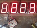
It works !...sort of. I now have 4 digits working. Now there is a different problem. when running, display 2 (numbering left to right) works but for come reason the segments that are off still glow if the same segment in display 1 is on. Displays 3 & 4 do the same thing. The second display is supposed to show a 2, but looks like an 8 because display 1 is a 0
Could it be to do with the cap on that controls the multiplexing ?
I have already tried swapping out the chip, but it didn`t make a difference.
Marz
westaust55
Moderator
I doubt it is the capacitor used for multiplexing (switching) between digits 1+3 and digits 2+4. If the capacitor value is significantly larger than specified you are likely to see slow switching between digits with two visibly on and two digits off for extended periods.
I presume that your display is showing constant values, ie the data in the SAA1064 is not being changed from the PICAXE?
From the display photo, while you might think that digit 1 is influencing digit 2 and digit 3 is influencing digit 4
if you consider digit 3 is a "2" and digit 4 is a "3" yet both segments "e" and "f" on digit 4 are glowing yet segment "f" is not on for digit 3.
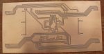
I tried to make sense of your photo of the PCB but not sure that I am right. Looking at the looping at the top and bottom for the 4 digits, it appears that you have the cathodes for digits 1 and 3 linked together and for digits 2 and 4 linked together.
Digits 1 and 2 should have common cathodes and likewise digits 3 and 4.
Post your schematic used as the basis for the PCB and folks here might better see/understand how it is all conencted.
I presume that your display is showing constant values, ie the data in the SAA1064 is not being changed from the PICAXE?
From the display photo, while you might think that digit 1 is influencing digit 2 and digit 3 is influencing digit 4
if you consider digit 3 is a "2" and digit 4 is a "3" yet both segments "e" and "f" on digit 4 are glowing yet segment "f" is not on for digit 3.
I tried to make sense of your photo of the PCB but not sure that I am right. Looking at the looping at the top and bottom for the 4 digits, it appears that you have the cathodes for digits 1 and 3 linked together and for digits 2 and 4 linked together.
Digits 1 and 2 should have common cathodes and likewise digits 3 and 4.
Post your schematic used as the basis for the PCB and folks here might better see/understand how it is all conencted.
Last edited:
marzan
Senior Member
Posted the wrong boardI tried to make sense of your photo of the PCB but not sure that I am right. Looking at the looping at the top and bottom for the 4 digits, it appears that you have the cathodes for digits 1 and 3 linked together and for digits 2 and 4 linked together.
Digits 1 and 2 should have common cathodes and likewise digits 3 and 4.
here is the circuit diagram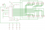
Marz.
westaust55
Moderator
Try adding say 10 kOhm pull-up resistors from the basse of Q4 and Q5 to the supply rail.
Needed to switch off the transistors in a positive manner when the SAA1064 is not directly turning them on via the NPN transistors.
Needed to switch off the transistors in a positive manner when the SAA1064 is not directly turning them on via the NPN transistors.
marzan
Senior Member
Hmmm.. guess I should have put 10k resistors ???What switches Q4 and Q5 off?
Marz.
I would take the resistors one step further.
Loose R1 and R3, place a 1K resistor between pin 14 and base of Q1, and a 10K pullup on the base of Q4 to V+, and a wire jumper in the place of R3. Then do the same for Q2 and Q3.
You will need to cut a couple of tracks for the 2 x 1K resistors and solder them to the bottom of the board, get it all working with modding your current board before you go making a new board
westaust55
Moderator
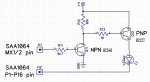
Another possible solution would be as per the attached partial schematic.
As suggested by SAborn, removing the resistor between the NPN emitter and ground allows the SAA1064 to turn the transistor on "hard" into saturdation so Vce is very low. With a resistor there, and around 8 mA flowing through the resistor the emitter would be 8 Volts above ground and the base about 8.7 volts above ground but as the SAA1064 MX pin may will only provide its supply voltage the transistor will not switch on fully and will not conduct sufficient current current from the PNP transistor base to allow the PNP transistor to provide full LED current if higher LED currents are selected (eg around 21 mA)
As suggested by SAborn, removing the resistor between the NPN emitter and ground allows the SAA1064 to turn the transistor on "hard" into saturdation so Vce is very low. With a resistor there, and around 8 mA flowing through the resistor the emitter would be 8 Volts above ground and the base about 8.7 volts above ground but as the SAA1064 MX pin may will only provide its supply voltage the transistor will not switch on fully and will not conduct sufficient current current from the PNP transistor base to allow the PNP transistor to provide full LED current if higher LED currents are selected (eg around 21 mA)
Attachments
-
 75.1 KB Views: 14

Perhaps the glow's being caused by the transistors not turning off fast enough, or the PNP transistors are connected the wrong way (they'll work, but badly). CHeck that the PNP transistors are in the right way and if that doesn't fix it, try different transistors.
Also make sure that the supply voltage is correct - this can be finely adjusted by using a switching regulator. If the transistors run hot, then the voltage is too high.
Also make sure that the supply voltage is correct - this can be finely adjusted by using a switching regulator. If the transistors run hot, then the voltage is too high.
marzan
Senior Member
Yer I tried it Pete. Same deal.Have you tried the code example i emailed you some time back to see if its a code problem or a hardware problem.
I well expect a hardware problem.
Marz.
Hi Marz,
Possibly a little current is leaking out of the SAA's "Anode Drive" pins so pull-down resistors may be needed.
However, IMHO generally the best way to cure a problem like this is to add resistors across the base-emitter junctions of either the NPNs or PNPs (or both as "belt and braces"). Make the value about the same as the resistor driving the base (i.e. 4k7 and/or 1k in the diagram in #66). This will keep more current away from the base when it's supposed to be OFF but won't drain unnecessary current when ON (because once the voltage gets to about 700mV, all the residual current goes usefully into the base).
Cheers, Alan.