Clocking Relay

Minifig666

Senior Member
Hello,
I know this isn't a very PICAXE related project but it may be involving a PICAXE later...
What I want to do is have a relay to switch on and off at no more than 10Hz. I understand there is a way to do it by charging and discharging a capacitor but all of my attempts so far have been fruitless. All I have been able to do is have it act as a standard relay 'vibrator' but for a short amount of time until the capacitor is fully charged. Does anyone have a schematic to make this work?
Thanks in advance. :)
 

eclectic

Moderator
Could I ask:
Why do you wish to switch a relay at this speed?

1. Is it capable / safe to switch at this frequency?

2. A Picaxe could easily cope with 10Hz switching,
using say a transistor or ULN2003.

Perhaps you could supply
some more information about your project?

e
 
Last edited:

BeanieBots

Moderator
A relay at 10Hz:eek:
Assuming you have a good one that is rated for 1e6 opperations, it will last just over 24 hours:(

Anyway, it's your relay.
Wire the relay coil in series with the NC contacts.
That will give you the 'vibrator' that you already have.
Now add a capacitor across the coil.
That will give an extra delay to the turn off. (t=RC where R ~= coil resistance)
To add delay to turn on for closer to 50% duty, add a resistor in series with the NC contacts and coil/cap. Rmax =~1/4 coil resistance.

et voila, oscillator with defined frequency & duty using nothing more than relay, resisitor and capacitor.
 

Minifig666

Senior Member
Sorry, I forgot to put anything about my project. It is to be the clock in a relay computer/ adder. If you hadn't have noticed I said no more than 10Hz. I want nothing solid state to be involved. The reason I said no less than 10Hz is because the relay 'vibrator' circuit (where a relay shuts of its own coil then energises its self then shuts its self off and so on) is too fast. It is safe I assume as it is switching very little current. It would be more preferable to have it running at about 2Hz but that would need a very big cap. Sorry, I should have really given more info.
 

Minifig666

Senior Member
Ok, I think I get it now. I was been a bit stupid and putting the capacitor in series with the coil and have its discharges power the coil, silly me. Thanks!
 

BeanieBots

Moderator
It is safe I assume as it is switching very little current.
Not really a question of 'safety' but a relay is mechanical, it has moving parts, those parts can only move X number of times before they break.
Typical figures (for a good relay) are ~1e6.
Even down at 2Hz you are only looking at ~1 week life expectancy.
Have a read of the relay datasheet to get better figures.
 

slimplynth

Senior Member
Not really a question of 'safety' but a relay is mechanical, it has moving parts, those parts can only move X number of times before they break.
Typical figures (for a good relay) are ~1e6.
Even down at 2Hz you are only looking at ~1 week life expectancy.
Have a read of the relay datasheet to get better figures.
Wonder how long it would be under continuous operation in a 28 day period? Perhaps the 1 million toggles give a working life for the relay computer of three months/a year?. I guess if you got the £'s to spend on relays it's all good, pretty difficult to make a relay computer without them too :D

I recall a Vacuum Furnace operator who decided that a £15 thermocouple was too expensive to replace, until it failed mid run and scrapped off a £100K aircraft part. Even at @£15 a piece some items are still consumables.
 

hippy

Ex-Staff (retired)
I'd be interested in seeing the exact circuit. This was one of my first ventures into electronics using a large relay in a can and that gave a huge kick when touching it when the contacts opened and the coil discharged. I'm intrigued as to where you are dumping the back-EMF from the coil to, if you cannot use a solid-state diode.
 

papaof2

Senior Member
If the current is very small, then a reed relay may be appropriate. The cycle life (number of operations) may be greater than a standard mechanical relay because of the differences in design.

John

edit:
The contacts of the relays in this datasheet http://relays.tycoelectronics.com/datasheets/OMR.pdf are rated for 100 million operations (the mechanical life) at 100ua at 5VDC or 50 million operations at 1 to 5ma at 5VDC or 10ma at 12VDC, dropping to 10 million operations at 100ma at 12VDC. A reed relay of this quality won't be cheap, but it will provide good life in the intended application.

Some surplus telecom relays will be in this category - just be sure to check the specs.
 
Last edited:

BeanieBots

Moderator
Be carefull using reed relays in this manner.
The coil has a cap across it and the contacts charge the cap.
Hence, contact current is VERY high, outside the spec of most relays and will if anything result in even shorter life than expected.
Fitting a resistor in series does help to reduce the contact current but it is still (and needs to be) quite high if you want several hertz frequency.

The back emf gets dumped into the cap. (acts like a snubber with the coil resisitance) The resultant current is what holds the relay on for a period of time. With no cap fitted, the oscillation frequency is only limited by the mechanics and the flyback voltage can get very high and is likely to cause premature failure of the contacts.
You can fit a flyback diode. It will slow down the off time but not the on time with no cap fitted. It will have little effect on anything with a cap fitted if the cap is large enough to have much effect on overall speed.
 

KMoffett

Senior Member
You probably did this too...Google: astable relay circuit...or some variation, with no luck.
Since you want to stay with electromechanical oscillator, how about a automotive turn signal blinker? The new ones are "electronic", but you might be able find one of the old ones with a bi-metal switch element. Then again, I don't know how long they would last.

Ken
 

Minifig666

Senior Member
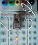
I am not realy accounting for back-EMF if I'm quite honest, but even Harry Porter's relay computer doesn't have anything, just a big cap on the PSU (I have attached an image showing just how powerful EMF is as the relay vibrator on my breadboard lights up a neon). By solid-stateless I meant without chips, I am using a 6A bridge rectifier and LEDs for the memory state indication. Having chips kind of detracts from the relay magic.

The relays I am using are:
SPST 20A@12V DC for the memory and one half of the adders (Overkill, but the cheapest from Rapid) They make a nice satisfying click.
DPDT 2A@12V DC for the adder.
They are both 10^5 electrical ops at full load (witch is 12A@250VAC for the SPDT but I'm not sure about the DPDT) and 10^7 mechanical ops.

I don't think a reed relay would quite have the current to clock it though.

As a matter of fact eclectic that is what gave me the inspiration for this, mine is based on his' relay computer 1 and another one I have seen on youtube before.
 

Attachments

Last edited:

fernando_g

Senior Member
A cam-driven switch. The cam is turned with an induction motor via speed reducing gears.
You probably could scavenge the required parts if you are able to find an old mains-powered wall clock.
 

papaof2

Senior Member
You probably did this too...Google: astable relay circuit...or some variation, with no luck.
Since you want to stay with electromechanical oscillator, how about a automotive turn signal blinker? The new ones are "electronic", but you might be able find one of the old ones with a bi-metal switch element. Then again, I don't know how long they would last.

Ken
Look for an old "heavy duty" flasher rated for "constant speed". These use a clock-type balance wheel and spring to set the flash rate and have a long life running at amps of current (as in flashing the turn signals on one side of a semi with a 53 foot trailer.

There is some minimum load required to make the device operate (don't have those specs); there were models for 12 and 24 volts.

John
 

Minifig666

Senior Member
"how about a automotive turn signal blinker"

Genius!
Tis a good idea actualy bit a bit arquard for me. I think aprox 1500uF is doing fine at 2 Hz.
Also with regards to the PSU for this project I am using a 12V tranformer witch actualy gives out 16V, when rectified it drops to 14V but when I put the filter caps on it jumps up to 20V is this because there is no load or because I have a transformer rated for 230V insted of 240? Any help?
 

eclectic

Moderator
Tis a good idea actualy bit a bit arquard for me. I think aprox 1500uF is doing fine at 2 Hz.
Also with regards to the PSU for this project I am using a 12V tranformer witch actualy gives out 16V, when rectified it drops to 14V but when I put the filter caps on it jumps up to 20V is this because there is no load or because I have a transformer rated for 230V insted of 240? Any help?
Hmmmm?

Could you please post the schematic,
and
a photo or two of your project.

I'm no expert, but others may be able to give
you some safety advice.

And, If I were you,
I would NOT use the circuit again,
until you have expert guidance.

Ec
 
Last edited:

Minifig666

Senior Member
Well frankly on the photo front you would be looking at 50M of wire, some asorted relays, resistors, a cap or two, a bridge rectifier and some other asorted bits still in their original packaging. I beleve the problem was a lack of load as adding a 12V bulb to the mix took it straight down to 12 ish (cheap trasformers mean poor regulation of course) however I did stupidly put a 16V cap on the rails (without load) and it went pop very quickly. When the trasnsformer is under no load the coils vibrate a lot particularly when my desk ampifies it, but quickly quiets down when you start drawing more than about half an amp. As for a schematic:

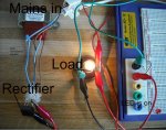
Mains-->12V transformer (Twin secondaries in paralell)-->6A 200V Bridge rectifer-->Load to shut the tranformer up-->Output

Sorry that is about the best I can give you at the moment.

I have take all of the precautians I can think of (Heat shrink, terminal shrouds, 3A fuse, a wooden partition betwen me and the transformer ect.). If you do want any photos of anything else though just ask. The finished product will be very similar to that of electronics and more's relay adder just with a few aditions. If there is a more stable way to set up my transformer please tell me, the one I have followed a steriotypical design. Thanks
 
Last edited:

eclectic

Moderator
Well frankly on the photo front you would be looking at 50M of wire, some asorted relays, resistors, a cap or two, a bridge rectifier and some other asorted bits still in their original packaging. I beleve the problem was a lack of load as adding a 12V bulb to the mix took it straight down to 12 ish (cheap trasformers mean poor regulation of course) however I did stupidly put a 16V cap on the rails (without load) and it went pop very quickly. When the trasnsformer is under no load the coils vibrate a lot particularly when my desk ampifies it, but quickly quiets down when you start drawing more than about half an amp. As for a schematic:

Mains-->12V transformer (Twin secondaries in paralell)-->6A 200V Bridge rectifer-->Load to shut the tranformer up-->Output

Sorry that is about the best I can give you at the moment.

I have take all of the precautians I can think of (Heat shrink, terminal shrouds, 3A fuse, a wooden partition betwen me and the transformer ect.). If you do want any photos of anything else though just ask. The finished product will be very similar to that of electronics and more's relay adder just with a few aditions. If there is a more stable way to set up my transformer please tell me, the one I have followed a steriotypical design. Thanks
I genuinely have no idea how your circuit is assembled.

Please post a schematic and photographs.

E
 

Minifig666

Senior Member
In the morning I'll get right to it. Sorry I make things sound a bit too complicated sometimes. My block diagrams clearly need work.
 

BeanieBots

Moderator
The voltage of a transformer is specified as RMS (root mean square) volts.
That is the voltage which if it were DC would give the same heating effect into a passive resistor. (the AVERAGE of AC is of course 0v).

The RMS voltage is ~1.4v (root 2) times lower than the PEEK voltage that will be seen at the crest of the AC waveform.

When AC is fed into a rectifier and then a capacitor, there will be a slight drop due to the rectifier but the capacitor (off load) will keep charging until it gets close the PEEK of the AC voltage which will be ~1.4 times its RMS voltage. When on load, the capacitor will slightly drop in volts after each crest passes. How much depends on the load and the capacitor value.

This is why you see a difference in voltage.
There is no way to make it more stable other than by using a regulator.
 

Minifig666

Senior Member
OK thanks that make sense as to why that cap went pop then.
I have attached the image of my PSU however I am missing the cap on the picture.
 

Attachments

Top