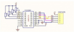
So instead of using the Toggle command to abbreviate the coding -not competent enough to really understand yet, I wanted to start off programming all four coils independently to learn how to do it. The driver board which came with the motor referenced above has a plug for the motor which has five leads, pins for four inputs from the controller, and a ground and power pin. The coding online for similar devices (can not read Chinese) that I can find shows eight steps
(which I can only assume is just repeated)? At the bottom is my code for these eight steps.
Result: It turned about 20deg over a long period of time- could not see movement with naked eye. Also LED lights for each motor leg do not make sense with inputs.
I took the eight steps below to be the inputs to the driver board from my controller-If they are the outputs from the driver board to the motor should I code the controller as if below values were inverted ?
The following picture is the control signal to drive a 28BYJ48 stepper to rotate 1/4096 circle.
line | 1 | 2 | 3 | 4 | 5 | 6 | 7 | 8 |
|---|
| red | 1 | 1 | 1 | 1 | 1 | 1 | 1 | 1 |
|---|
| orange | 1 | 1 | 0 | 0 | 0 | 0 | 0 | 1 |
|---|
| yellow | 0 | 1 | 1 | 1 | 0 | 0 | 0 | 0 |
|---|
| pink | 0 | 0 | 0 | 1 | 1 | 1 | 0 | 0 |
|---|
| blue | 0 | 0 | 0 | 0 | 0 | 1 | 1 | 1 |
|---|
symbol out1=C.0
symbol out2=C.1
symbol out3=C.2
symbol out4=C.4
symbol ctr1=b0
Start:
low out1,out2,out3,out4
Do while ctr1<2000
low out1,out2,out3,out4
'low out2,out4
high out1
pause 2
low out1
'low out2,out3
high out1, out2
pause 2
low out1, out2
'low out1,out3
high out2
pause 2
low out2
'low out1,out4
high out2, out3
pause 2
low out2, out3
high out3
pause 2
low out3
high out3, out4
pause 2
low out3 ,out4
high out4
pause 2
low out4
high out1,out4
pause 2
low out1, out4
ctr1=ctr1+1
loop
pause 5000
goto Start