CIRCUIT CHECK - UPLOADING PROBLEMS
- Thread starter rxhul
- Start date
lbenson
Senior Member
A "normal picture" could be 640x320 pixels on a very early digital camera to thousands by thousands of pixels. You can use Microsoft Paint to "resize". I find a horizontal width of 1200 usually maintains sufficient clarity. Make sure "Maintain aspect ratio" is selected. You'd usually want to save the resized picture with a different name.
Thank you very much lbenson, I think it worked!
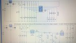
The top circuit is the development of the bottom one so I hope they both do the same thing.
I don't know why but I feel like my circuit is too simple (?) just 5 PTMS 5 LEDs a VR and a buzzer.
Would an analogue input spice it up a bit?? eg. using an LDR to act as a motion sensor?
To put this into context, this is for a fencing target which has three different modes the main one of which is one of the LEDs randomly comes on and the pressure pad placed above it is hit, the light goes out and the buzzer sounds.
The VR alters the speed setting.
Many thanks once again for all help.
Attachments
-
 351.2 KB Views: 33
A Darlington-pair isn't realy necessary. A transistor with a resistor works as well. Perhaps this article below would clear things out.
https://microcontrollerslab.com/active-passive-buzzer-interfacing-pic/
https://microcontrollerslab.com/active-passive-buzzer-interfacing-pic/
hippy
Ex-Staff (retired)
You posted your circuit at 17:38 GMT last night and asked at 04:51 this morning. That's overnight for those of us in the UK and Europe so a lot of people won't even have seen it until about now.Just wondered if anyone managed to have a look at the circuit to comment?
The only major error I can see in the top circuit is you have connected leg 14 "0V" to 5V / V+ rather than to 0V.
There's nothing wrong with simple circuits; its what it does which matters. In fact "the simpler the better" is a good design principle to follow.I don't know why but I feel like my circuit is too simple ... Would an analogue input spice it up a bit?? eg. using an LDR to act as a motion sensor?
Unless adding an LDR, having motion detection - if that even works, adds any value to what you are creating I can't see the point. And how would you add that anyway ? Just to spice-up the circuit; it's not necessary, just adds unnecessary complexity.
In respect of "simplest is best", your pressure sensors with pull-down resistors to B.5, C.0 to C.3 could use internal pull-ups and pads to 0V rather than 5V. That saves 5 resistors; even simpler.
I would move the pot to B.5 and use C.0 to C.4 for your five pressure pad inputs. That will make it much easier to read all five pads in one go with a 'b0 = pinsC & %00011111".
I would also wire the pot (VR) across V+/0V and take its wiper to B.5. That saves another resistor and it will be better than trying to use a 1K pull-up with a 47K pot.
I would also move the buzzer from B.0 / Serial Out to B.4, use B.0 to B.3 for your four LED outputs. That will make it easier to program in-circuit if you decide you want to do that, which is always recommended to have.
That does beg the question though; you have 5 or 6 trigger buttons but only 4 LED outputs ?
Code:
5V --.-----------.--------------------------.--
     |     _     |     .----------.         |
     |   _|_|_   `-----| V+    0V |---.     |
     `---o   o---.---->| C.5  B.0 |   |     |
     .---o   o---|---->| C.4  B.1 |   |     |
     }---o   o---|---->| C.3  B.2 |   |     |
     }---o   o---|---->| C.2  B.3 |   |    .|.
     }---o   o---|---->| C.1  B.4 |   |    | |
     }---o   o---|---->| C.0  B.5 |<--|---|| | 47K
     |          .|.    `----------'   |    |_|
     |      10K |_|        14M2       |     |
     |           |                    |     |
0V --^-----------^--------------------^-----^--lbenson
Senior Member
Just FYI, it's probably better to post pictures by clicking the "Picture" icon (sun & mountain) rather than the "Attach files" button. The attachment button is better for PDFs or zip files or code too long to include in the code box.Just wondered if anyone managed to have a look at the circuit to comment?