Car oil pressure - how to measure with Picaxe?

GreenLeader

Senior Member
My car has a VDO electric oil pressure gauge. I would like to take (piggyback) the signal from the existing sensor into an an ADC on a Picaxe for logging.

Trouble is I don't understand the principle of operation of the gauge and have not been able to turn up much useful stuff on automotive instrumentation on the Internet.

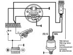
The gauge spec is 0-100psi and 10-184 Ohms, and a schematic is attached. It has a switch output to drive a warning light and the analogue output to drive the gauge needle.

The question is: how can I get a voltage signal out of the sensor to log with a Picaxe ADC, without interfering with operation of the gauge?

Could anyone offer any tips?
 

Attachments

Jaguarjoe

Senior Member
Feed your Picaxe from the (S)G terminal on the gauge sender unit. The Picaxe won't load it down so it won't affect the gauge operation. Just make sure the voltage doesn't exceed 5 volts otherwise you'll kill the Picaxe. If it does exceed 5 volts you'll need a voltage divider.
 

MFB

Senior Member
I would suggest that you measure the output voltage range from the pressure sensor before getting anywhere near connecting a PICAXE. It may be possible to drive an ADC input via a simple two resistor potential divider but, even if the pressure sensor outputs 0-to-5V, you should at least include a 10K series resistor to protect the PICAXE. It may not be a problem if the output was (say) 1-to-3 volts because a 10bit reading could still give adequate resolution.

You will of course need to use a common ground and also regulate/protect the vehicle supply to the PICAXE.
 

hippy

Ex-Staff (retired)
As with all automotive projects, you should also be considering the effects of huge spikes, both positive and negative, which can destroy the PICAXE and any power supply you're using.

A forum search should turn up more information on automotive use. The general consensus is that if you don't know what you're doing or don't understand the implications of the potential consequences, don't do it.
 

Shack

Member
Most OEM signals I have seen are 0-12V for oil unless they run back to the ECU. And, they are not linear. Spikes and transients are not an issue; however, you will have a very difficult time if you tie into the sensor signal line and then try to translate it if it is 12v.

A better approach is to add another sensor and use your own 5V circuit. Most of the oil pressure VDO senders are 0-5 Bar = 80 PSI. I use a Siemens VDO Sender # 360-003. If you can get the number you can verify and your car shop manual should tell you and give you the voltage v. pressure chart for testing.

Ground the one side of the sensor, and run the other back to the Picaxe AD with a 100 ohm pull-up to +5V.

Here is the code for the Picaxe for that setup:
PSI = 31,578 / (950 – ADC) – 37
(93 <= ADC <= 653) Kick these out ... not accurate.
 

wapo54001

Senior Member
If you are going to be logging data and you want accuracy, the VDO will not provide it. It, and most resistive pressure sensors including the Stewart-Warner, are abysmal in that regard.

May I suggest that you look at an (easily found on the Web) Auto Meter 2246 -- 5vdc, 0-100psi, .5v~4.5v ratiometric output, with 1%FS accuracy? About $100 if you buy it online, but if you find it or an equivalent at a junk yard, of course much cheaper. It is a very common part in relatively modern vehicles. It will be 1/8"NPT, and require an electrical harness that works with a Packard Connector which is very commonly found in automobile engine compartments. Many companies build the same sensor, Auto Meter is the aftermarket supplier.

It will give you an 800-count resolution (4V) and will run off the Picaxe regulated 5vdc power supply. Draws about 7ma. Use a 10K resistor between the sensor output and the Picaxe input. Take the count and subtract 102 to eliminate the .5v offset, then mathematically convert the 0~819 count range to 0~1.000 volt output range and use an integrator circuit to give you the analog voltage. Result is overall 2% accuracy and .2psi resolution.

Since you're going to use this setup in an automotive environment, get an "automotive qualified" regulator. I use the LM2931 adjustable output variety because the Auto Meter 2246 is ratiometric -- accuracy depends on the accuracy of the 5vdc source.

Hope this helps. I've been chasing this particular grail for quite a while now.
 

wapo54001

Senior Member
If you want to stick to using the VDO sensor, use the voltage divider calculator located here:

http://hyperphysics.phy-astr.gsu.edu/hbase/electric/voldiv.html

1. Make a precise measurement of the battery voltage at the oil pressure gauge.

2. With pressure at zero, measure the precise voltage on the high side of the VDO sensor.

3. Disconnect the sensor from the gauge at the sensor and measure the actual resistance from the post to the case (ground) because it could be several ohms off 10 ohms.

4. Use the website mentioned above, and

a) plug in the full battery voltage to V1

b) plug in the zero pressure resistance of the sensor for R2.

c) play with resistances for R1 until Vout equals the voltage you measured at the junction of the sensor and gauge.

The value of R1 when the calculated voltage and the measured voltage match should be the DC resistance of the gauge (probably set by a fixed resistor in the gauge).

You can then plug in the theoretical high end resistance of the sensor for R2 and the difference in Vout between 10 ohms and 180 ohms (?) will give you the voltage range at the gauge for the range of pressure that can be measured by the VDO.

Good luck.
 

GreenLeader

Senior Member
Many, many thanks for the comments and suggestions - as always this forum is very effective in solving problems or giving leads to follow.

I realise I need to watch out for voltage spikes, just haven't got to that part of the project yet - still working on the sensor circuits and code for logging to EEPROMs. I may well ask for anti-spiking help later :)

wapo540001 - I am probably going to stick to the VDO sender unit for now - want to minimise cost & plumbing modifications. Accuracy is not too much of a concern but repeatability is important. I want to be able to trend data to detect significant (+/-5psi) losses in oil pressure at given temperature/rpm. Do you think the VDO units are capable of the level of repeatability?
 

wapo54001

Senior Member
Greenleader,

Sorry, I can't speak to precise repeatability values. Your need translates to +/- 5% of full scale (100psi). Frankly, I don't think you can achieve that or it will be marginal. In the case of the Stewart Warner sensor, the potential absolute error at the high end was around 20% as I recall.

These resistive sensors are crude indicators, not a basis for an accurate datalogger. Personally, I would not use a resistive pressure sender for any serious data collection.

What is your general oil pressure? I ask because I think you will find that repeatability is better as the pressure goes higher. At lower pressures, my experience has been that the resistive sensors like the VDO are "sticky" and respond better as the pressure goes higher.

If your oil pressure is 20psi and below, I'd say your in the worst range of the sensor.

I really would encourage you to go to a junkyard and get a modern sensor out of a wrecked car. A friend who knows these things says that you should be able to get one for $10~$15 at a junkyard. It would have a three-wire connection with a Packard connector (cut the wiring harness and get the matching connector), and the sensor would look like this one:

http://btfsystems.com/fp/sensors_compared.jpg

(The larger of the two is the Stewart Warner, by the way.)

And the 08M coding would be a whole lot easier, since the sensor is completely linear with an error band of 1%FS, and will give you a full 4.0 volt swing from 0~100psi which translates to 100psi divided by 819 ADC count, which will yield better than .2psi resolution with really excellent repeatability.

I have built a board that uses an automotive grade regulator and an 08M using an integrator circuit for very accurate output, and outputs the 100psi as 1.000 volts to be read on a dpm or dvm, . If you use a panel meter, you can set the decimal point to make 1.0 volts read as 100.0psi. Lascar has a range of small panel meters (.7"Hx1.4"L) that can be mounted with a single 7/32" hole which is very convenient to mount practically anywhere.

You can see my board here:

http://btfsystems.com/fp/circuitcard.pdf

And the lascar meters here:

http://btfsystems.com/fp/gizmo.jpg


If you want to do the same, do a search here on "integrator" and wilf_nv. You will find his explanation which helped me a lot. Good luck with your project.
 

GreenLeader

Senior Member
OK, I'm convinced :) - I'll see if I can find a second hand sensor of the type you mention. Any idea about what cars use these sensors?

Thanks for posting the pictures of your project and for your advice - it looks like you've done all the hard yakka (work in Oz-speak) so I don;t have to!
 

wapo54001

Senior Member
I'm told that vehicles after 1985 use them, but try for a late model car. Be careful you don't get a pressure "switch" that only turns on/off at a given pressure.

A mechanic told me to look on the engine block or head for oil pressure, and on the fuel injector rail for fuel pressure sensors. Modern fuel injection is high pressure, so I would expect those to be 100psi units as well.
 

GreenLeader

Senior Member
Finally bit the bullet and bought a brand new autometer 2246 100psi pressure sensor. Did not have much luck in junk yards over here.

My car logger has been working fine for about 10-20 hours of engine run time, so not trouble with spikes so far.

So I will now add the 2246 and bench test it before I plumb it in. So thanks to wapo54001 for posting the details of sensor output - the autometer site is decidedly bare of anything technical...
 
Top