Followed someones instructions to connect aluminium foil to pin C.2 on the 18M2 project board for the touch pin which is going to be used as a capacitive water level indicator. i came across a thread on the forum and they connected one piece of foil to ground and the other piece of foil to the C.2 pin but when calibrating the touch sensor there isnt anything being picked up, has anyone got any suggestions on fixing this problem?
capacitive water level sensor using touch pin on 18m2
- Thread starter dan123456
- Start date
Hi,
IMHO you're probably getting out of your depth.")
Is your "foil" totally insulated from the water ?
A capacitor dielectric (i.e. the bit between the plates) generally needs too be an insulator. But in the context of the PICaxe Touch circuits, water is almost certainly a "conductor". In any case, water has "complex" dielectric properties which probably will be difficult to process reliably (if at all).
However, I'd also like to see the thread you found.
Cheers, Alan.
IMHO you're probably getting out of your depth.
Is your "foil" totally insulated from the water ?
A capacitor dielectric (i.e. the bit between the plates) generally needs too be an insulator. But in the context of the PICaxe Touch circuits, water is almost certainly a "conductor". In any case, water has "complex" dielectric properties which probably will be difficult to process reliably (if at all).
However, I'd also like to see the thread you found.
Cheers, Alan.
erco
Senior Member
The touch sensor values vary so wildly with humidity and other factors it's hard to believe you would get any useful reading from such a setup. How about another sensor, maybe an ultrasonic sensor looking down at the water or a tape sensor like https://www.parallax.com/product/29131
Thanks for the advice, here is the link to the original post: http://www.picaxeforum.co.uk/archive/index.php/t-17328.html
Hi,
So have you reproduced the sensor exactly as described in that post (i.e. with two strips on the outside of a plastic jug) ?
What values does TOUCH16 c.2,w1 actually return for different levels ? Tip: use for example: SERTXD(cr,lf,#w1) ...... with the PE terminal.
Personally, I would make the effective "ground" connection much larger. As a minimum, run the "touch" strip between two others connected to ground. Or maybe even make the bottom of the jug/tank the "earth" and run a single strip vertically outside, or fully insulated inside the tank.
But calibration and repeatability are likely to be a major issue so, as suggested, an ultrasonic method, for example, is more likely to be successful.
Cheers, Alan.
leekelso94
New Member
thanks for the suggestions, I have purchased the SFR005 ultrasonic finder sensor instead of the capacitance idea, but not entirely sure on what to make of the readings when simulating sample code that was attached in a manual, when running the code a side window on picaxe editor opens and shows me what has been sent/picked up by w1 and each time the code is run its always the same numbers that appear here, can anyone explain t me what this means?
thanks
thanks
erco
Senior Member
Do you mean in the PE simulator? Without a sensor or Picaxe attached?not entirely sure on what to make of the readings when simulating sample code that was attached in a manual
leekelso94
New Member
thanks for the reply, I mean when the sensor is connected to the picaxe 18m2 project board using an I/O pin and a simulation is run with the sensor connected to the project board the picaxe editor will open a side window to show what has been received from W1 but only bits 1 2 and 3 have values but these values are always the same and it is this that is confusing me
erco
Senior Member
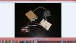
Attach your code and a photo of your setup. Could be a code or wiring error, but these modules work well and are simple to use once you understand them.
https://www.youtube.com/watch?v=-6leQnKHJF8
https://www.youtube.com/watch?v=-6leQnKHJF8
leekelso94
New Member
the code tat is being run is just a sample code that was found on a manual I came across, symbol trig = C.2
symbol range = w1
main:
pulsout trig,2
pulsin trig,1, range
pause 20
let range = range * 10 / 58
debug range
goto main
the set up is bellow
symbol range = w1
main:
pulsout trig,2
pulsin trig,1, range
pause 20
let range = range * 10 / 58
debug range
goto main
the set up is bellow
leekelso94
New Member
the code is a sample code I found
symbol trig = C.2
symbol range = w1
main:
pulsout trig,2
pulsin trig,1, range
pause 20
let range = range * 10 / 58
debug range
goto main
the set up is
symbol trig = C.2
symbol range = w1
main:
pulsout trig,2
pulsin trig,1, range
pause 20
let range = range * 10 / 58
debug range
goto main
the set up is