Cant download prog to 18m2

Simbad

New Member
In conclusion, you can programm picaxe with MCP2200 , but be sure it is latest revision chip.


The Microchip MCP2200 does not correctly support the 'RS232 break' feature and cannot be used to program PICAXE chips.
Use a Prolific or FTDI based cable, ideally the AXE027.
I have to disagree with Technical, MCP2200 can be used to program Picaxe, here is proof.
In that case you have a later version firmware MCP2200 (and/or driver) than we do, we have early demo kits that definately don't support the break command.
Or, considered the other way, Microchip actually listened and fixed the issue when we complained about the missing break support in the driver over a year ago!

Anyway, its good to hear that the later version firmware/drivers do now work.
.


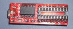
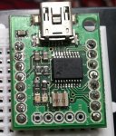
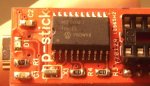
Iam trying to use this http://web.argus.lv/shop/download/436689/hwindex.htm to communicate with my 18m2. This is mcp2200 chip based converter.


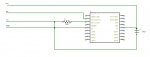
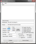
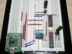
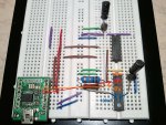
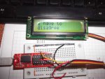
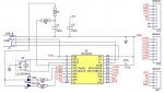
Connected like told in tutorial with 10k 22k resistors, got hello message in terminal from pic, but unable to download prog. In this case coneverter is set to "invert uart" in MCP2200 Configuration Utility , because without this it spoke to me in chinese. Backloop in terminal(putty) works fine, 2 flashing leds, red sent,orange recive. Then tried to disable invert in software and make curciut with hcf4049ube hex inverter, same result, got hello but no download - no leds are active during download attempt. Tried hard reset bunch of times. Tried without inverting logic. Port test green led : off <0, on +5v. 18m2 v+ supply from converters +5.

UPDATE1:
http://www.picaxeforum.co.uk/showthread.php?21246-Cant-download-prog-to-18m2&p=205244&viewfull=1#post205244

UPDATE2:
http://www.picaxeforum.co.uk/showthread.php?21246-Cant-download-prog-to-18m2&p=205260&viewfull=1#post205260
 

Attachments

Last edited:

Svejk

Senior Member
Use only one resistor for programming port, the 10k to ground, the MCP2200 should be configured as inverted signal, disable RTS/CTS. As the output is at TTL level, the 22k is not required. Add a 100 nF as close as practical to the power pins of picaxe.
 

inglewoodpete

Senior Member
The MCP2200 USB-to-serial chip is new to me. I have not heard of it being used with a PICAXE before. It is possible that it could be configured to work with the Programming Editor and a PICAXE.

Perhaps there are other forum members who have had success with the MCP2200 but have kept it quiet.:)
 

Svejk

Senior Member
I forgot to mention: here is my USB Picaxe Prototyping Stick using MCP2200. It is setup as mentioned in post #4.

pstick_m.jpg
 

Simbad

New Member
Use only one resistor for programming port, the 10k to ground, the MCP2200 should be configured as inverted signal, disable RTS/CTS. As the output is at TTL level, the 22k is not required. Add a 100 nF as close as practical to the power pins of picaxe.
Did I connect correctly? Without invert check box i got 5v on green led off and <0 on on, when invert on - the voltage is aroud 0+-. i have big multimeter so i cant measure mv. Idont have 100nF at the moment, tried 10nF on pic and 10uF, nothing... Is exactly 100nF necessarily?

Protoboard


Schematic (didnt found m2 in designspark,used 18)
schematic.JPG

MCP2200
mcp2200.JPG

Video(time lag due my pc+recording)
 
Last edited:

Svejk

Senior Member
Yes, that should be it. The 100 nF is highly recommended, although the value isn't exactly critical. Try close to 100 nF if you don't have one, 47 nf or 220 nF etc.

Inverted signal means you are geting 0V at mark (that is idle, logical 1) and 5V at space (logical 0). As you stated you are getting that. To prove that the MCP2200 works, short Rx and Tx and test with a terminal, what you send is what you receive. Once you know the MCP2200 is working, then only Picaxe connections are left to be checked.

Please post a photo and a schematic of your setup.
 

Svejk

Senior Member
Your setup appears to be correct. Add #picaxe 18M2 at the top of your program. Check the voltage at serin pin without anyting runing, but with MCP2200 connected. It should read 0V. Most likely is noise in power line.
 

Simbad

New Member
The laptop on which Iam right now has power issues, sometimes opical mouse usb adapter needs to be switched or pressed hard to work again, power socket drops charching mode(fast switching), sleep indicator is on when pc is runnig,yesterday got random shutdowns... there maiby huge noise in usb sockets. Tommorow I will test on other PC, hopefully that was the problem. Stay tuned for updates.

P.S. MCU is 18M2, reinstalled IDE , add #picaxe 18M2 - no sucess, backloop on MCP2200 works fine - 2 leds are blinking and i get message what i sent.
 

Simbad

New Member
I still need your help. MCP2200 ivertion didnt give 0-5v drop on green led test. It is 0+-, doesnt matter on or off
So I tried again to make circuit with inverter, like this

hex-inverter.jpg

New caps that i used was 0.68uF (on pic are 10uF). Got 0-5v drop on port test(green led), but actualy it was 1-2 off to 5v on. Still can recive Hello on new pc, but no luck to download.

2Svejk can you please share full schematics how to connect with inverter like I did (invert UART in mcp2200 is off). Because as is said invert UART in mcp2200 config doesnt give that 0-5v drop that it should(why?).
And what is V on tx-gnd and rx-gnd converter with invert on and off?
 

Svejk

Senior Member
Simbad, if you receive the Helo message then your MCP works fine.

See attached.

hex-inverter.jpg

If still no joy, power the picaxe with 3 fresh AA bateries and make common ground with MCP2200, then try to program.
 

Technical

Technical Support
Staff member
The Microchip MCP2200 does not correctly support the 'RS232 break' feature and cannot be used to program PICAXE chips.
Use a Prolific or FTDI based cable, ideally the AXE027.
 

Goeytex

Senior Member
The MPC2200 Data Sheet states that the maximum capacitance on the Vbus line should be no more than 10uf to
prevent excessive surge current at power up. This surge current could cause the MCP2200 USB port to shut down.
You need to reduce the capacitor values to be within specification.

Suggest a 4.7u near the adapter and a 100nf across the Picaxe and 100nf across the inverter IC.

To see if the Port is shutdown .... Plug the Cable in. Wait several seconds. Go to device manager.
Disable the related com port. Wait 10 seconds. Enable the Com port. Then run PE serial test again.
IF it now works then the Port was shut down by the OS.

I cannot find where the MCP2200 supports break signaling. If it does not then it cannot program a Picaxe.
 

Simbad

New Member
The Microchip MCP2200 does not correctly support the 'RS232 break' feature and cannot be used to program PICAXE chips.
Use a Prolific or FTDI based cable, ideally the AXE027.
How Svejk managed to programm using MCP2200 remains a mystery.
 

Technical

Technical Support
Staff member
In that case you have a later version firmware MCP2200 (and/or driver) than we do, we have early demo kits that definately don't support the break command.
Or, considered the other way, Microchip actually listened and fixed the issue when we complained about the missing break support in the driver over a year ago!

Anyway, its good to hear that the later version firmware/drivers do now work.
 

Svejk

Senior Member
The config tips were confirmed in post #8, the MCP2200 seems to work fine (post #11):

backloop on MCP2200 works fine - 2 leds are blinking and i get message what i sent.
However, power supply might be the cause for not downloading the program. There is still no decoupling cap at power pins. Without more in depth investigation on Simbad side is hard to say. Once I've had a bad contact from breadboard pins for example, it was hours until I found the issue.
 

Simbad

New Member
The config tips were confirmed in post #8, the MCP2200 seems to work fine (post #11):
However, power supply might be the cause for not downloading the program. There is still no decoupling cap at power pins. Without more in depth investigation on Simbad side is hard to say. Once I've had a bad contact from breadboard pins for example, it was hours until I found the issue.
When downloading does the any led is blinking? Tried with 3 aaa batteries, gnd to mcp2200 gnd, reinstalled drivers. Nothing. Still when hitting programm, rx(hello message) led stops blinking for 5 secs and error message pop up, rx starts again.

2Svejk MCP2200 is set to invert signal. V that MCP is sending on green led test is 0.00-0.01V (tx-gnd) - on and off,doesnt matter, picaxe input recives this signal 0.00-0.01V, Its getting a real pain to get this thing working...
 

Technical

Technical Support
Staff member
that MCP is sending on green led test is 0.00-0.01V (tx-gnd) - on and off,doesnt matter, picaxe input recives this signal 0.00-0.01V, Its getting a real pain to get this thing working...
This is a symptom of the 'RS232 break' feature not working, and is also exactly what we found when we tested this chip several months back.
It would be very interesting to compare the chip markings on Svejk and Simbad's chips (a good way is to take a digital photo if you can't see with naked eye).
We strongly suspect it may depend on which 'version' MCP2200 you actually have.
 

Simbad

New Member
This is a symptom of the 'RS232 break' feature not working, and is also exactly what we found when we tested this chip several months back.
It would be very interesting to compare the chip markings on Svejk and Simbad's chips (a good way is to take a digital photo if you can't see with naked eye).
We strongly suspect it may depend on which 'version' MCP2200 you actually have.
My chip

mcp2200.jpg
 

hippy

Ex-Staff (retired)
Looking at MCP2200 errata Simbad's is version A1, mine is A2.
It is interesting that the errata does not mention the break signalling issue, but then break signalling is not mentioned in the MCP2200 datasheet either.

From post #4 it seemed break was being carried on the A1 when the polarity was not configured as inverted ( though with the polarity opposite to what the PICAXE requires ), but not when the polarity is configured as inverted. It would be worth Simbad removing the PICAXE circuit and repeating tests with just the MCP2200 to confirm that behaviour for both polarities .

One would expect a change of behaviour between A1 and A2 silicon to be mentioned in the errata so it could be that break signalling is not officially supported but just happens to work better on the A2 silicon.

It would be worth making sure the latest configuration program is being used in case it's simply an issue of earlier versions not setting the chip's configuration bits correctly. That could explain lack of mention in the errata ( was always working, but not set to work ) but I suspect it's clutching at straws.
 

Technical

Technical Support
Staff member
Ours is also A1 firmware, we'll order an A2.
The other thing to check is the 'usbser.sys' file revison, particularlay on XP (which requires 2 hotfixes as per Microchip documentation).

Edit:
Hippy is 100% correct.
On our A1 firmware when the 'invert UART polarity' checkbox is checked the break function (ie the green LED test) does not work. This is why we stated it did not work, as this was our test setup.

However when the 'invert UART polarity' checkbox is not checked break does then actually work. So break does sometimes work on the A1 revision, but only under certain settings (ie when not inverted, which is not helpful for PICAXE users).

So basically give up on A1 firmware, make sure you have A2!
 
Last edited:

hippy

Ex-Staff (retired)

Simbad

New Member
With all the problems you have had with the MCP2200, all the problems and hoop jumping noted on the forum in trying to use non Rev-Ed cables, one has to wonder why you are not one step away from ordering an AXE027?

Especially as that is considerably cheaper.
I dont know why but i thought it had price like £27, is it 9.99?!
 
Top