Can PICAXE outputs only be HIGH or LOW?
- Thread starter abenn
- Start date
However, the DAClevel command cannot be used with an LED
M.2, p.52
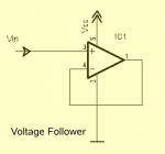
"Note that the DAC MUST BE BUFFERED for
reliable use. It cannot, for instance, provide
enough current to light an LED. It is purely a
reference voltage for use with, for example, an
op-amp configured as a voltage follower.
"
e
M.2, p.52
"Note that the DAC MUST BE BUFFERED for
reliable use. It cannot, for instance, provide
enough current to light an LED. It is purely a
reference voltage for use with, for example, an
op-amp configured as a voltage follower.
"
e
Thanks for so many replies so quickly ")
PWM and DAC both look promising. I know what PWM is, but what's DAC? I'm happy to experiment with code for a while -- I'll come back if I get stuck!
What does buffering mean in this context? In fact my 08M2 is driving a 2N2222A with a base-load resistor (can't remember the value) to drive the LED -- that should respond to the voltage generated by the DAC commands, shouldn't it?
The output current of the DAC is feeble. A buffer (such as an op-amp) is required for driving anything, but the DAC can just be connected straight to things that only require a voltage, such as an ADC input.Thanks for so many replies so quickly
PWM and DAC both look promising. I know what PWM is, but what's DAC? I'm happy to experiment with code for a while -- I'll come back if I get stuck!
What does buffering mean in this context? In fact my 08M2 is driving a 2N2222A with a base-load resistor (can't remember the value) to drive the LED -- that should respond to the voltage generated by the DAC commands, shouldn't it?
Using PWM would be better than using DAC for driving a transistor because with DAC the transistor will be in a 'semi-on' state causing it to get hot (when driving high loads) whereas PWM will make it alternate between being completely on and completely off making it run cooler. Lower PWM frequencies are a bit better because of a short transistion time between on and off.
What is a buffer in this context?
What op amp? LM324 quad or a dual or a single single voltage rail.
http://www.ti.com/lit/ds/symlink/lm124-n.pdf
Pages 10 to 19 give you the standard applicaton circuits to save on the grey cells. Page 13 fig 11 is the voltage follower, or buffer circuit. A quad op amp can give you four such circuits. The devices are probably still very available in DIP packages, but I notice the move to surface mount seems to be catching up on my datasheet browsing of late.
Page 11, Figure 5 LED Driver. either use one opamp as a buffer and feed the LED driver or see if putting a link from before the LED current limiting resistor gives you a voltage follower/LED Driver composite or fails to operate quite as expected.
Dig in.
westaust55
Moderator
How many levels/steps of intensity do you want.
One or many LED's ?
The WS2801 is capable of driving 1 RGB or 3 mono (single colour) LED's and daisy chain for more LEDs. If only 1 mono LED could be slight overkill.
using 2 IO as an SPI type interface, you can set the LED current with a resistor and PWM is used to set the level in 256 steps from off to full brightness.
See some recent work here: http://www.picaxeforum.co.uk/showthread.php?22713
Thanks. I'm using the single-transistor interface that they show in the standard application circuits, except using a 2N2222A instead of the one they show -- can't remember why I chose that, but it's worked satisfactorily for me thus far.
Unfortunately, so far as modern electronic devices are concerned, my experience only goes as far as discrete transistors and other basic components plus, of course, the PICAXE itself. So, what is an op amp? From the leaflet in your link, Paix, each of the four sections of it seems to behave exactly like a single transistor, and requires the same number of external components. Is it used simply because of the convenience of having multiple devices in one package?
It seems to be similar to the "Darlington Driver IC" shown in the PICAXE interfacing circuits pages, except the Darling Driver includes the associated base-load resistors etc.
But I digress! Back to my original question ... I'll be trying out the PWM command as soon as I get a chance to have a session in the workshop, and see how it works with my transistor-driven led. I think I understand the way they've used PWMOUT and PWMDUTY in the example in the manual, so I can edit their basic program on p.167 to achieve what I want.
Edit: I've copied the brief program, and edited it to include more steps from 150 down to 0, and have got the basic effect I was wanting. Thanks to all of you for pointing me in the right direction.
Last edited:
The benefits of having four opamps in the one package is pretty much convenience and given the basic circuits in the datasheet, it is a very universal component, far beyond the capabilities of a single transistor, so flexibility is a big part of the equation. Given my self trained electronics skill, I have to admit that whist I can use transistors, but am more likely to struggle than if I was to implement the function with a simple single rail opamp.
That said, I am only today thinking of downloading LTSPICE and doing some real refresher work. I haven't used SPICE before and last time I really looked it was a coster and Windows only - quite some while ago.
The 2N2222A is, I think, just a little beefier than your average general purpose NPN transistor, but a good choice and was always the GP NPN device of choice in the USA, rather than our own BC108 and later preferred devices.
Thanks for replying again. I'm still struggling with these technical terms ... is an NPN transistor a basic kind of op amp, and is the "Darlington Driver" mentioned in part 3 of the PICAXE manual simply several op amps installed in a single package with common + and - terminals?
2N2222A is cheaper than BC108 (at Farnell at least), but a ULN2803 8-NPN Darlington array is cheaper than both of them Looks like I'll have to catch up with the times -- a device like that must make my PCB layout simpler, and soldering a single DIL socket is much easier and less risky than several discrete transistors.
2N2222A is cheaper than BC108 (at Farnell at least), but a ULN2803 8-NPN Darlington array is cheaper than both of them
Looks like I'll have to catch up with the times -- a device like that must make my PCB layout simpler, and soldering a single DIL socket is much easier and less risky than several discrete transistors.Have a look at this web site. It looks at transistors at a non technical level.
http://www.kpsec.freeuk.com/components/tran.htm
Also note the Darlington towards the bottom of the page, two transistors connected together to give a higher gain.
The ULN2803 is a chip containing 8 of these devices. Note it is a "low side" switch, such that taking the input high, will cause the output to go low.
Err, you are going to breadboard first?snip
snip
-- a device like that must make my PCB layout simpler,
and soldering a single DIL socket is much easier and less risky than several discrete transistors.
I hope, for your sake.
e
Hi,
To answer a few questions: BC108 is expensive because it still uses a metal can, BC548 is basically the same chip in a plastic package so cheaper.
The basic "Darlington" configuration is two transistors connected with common collectors and one emitter to the other's base. It basically behaves as a very high gain transistor, but with a higher "VBE" (~1.3 volts base to emitter). The ICs contain several of these, with additional resistors, but the common ground makes them unsuitable for buffering the DAC (Digital-Analogue Converter) signal.
An Op Amp (in unity gain configuration) is the "natural" choice to buffer the DAC signal, but it must be a suitable type of Op Amp (single rail and good rail-to-rail input and output swings, etc.).
If you're more comfortable with transistors, then use an NPN in an "emitter follower" configuration, or two in series (basically then a Darlington). But personally I'd probably use a PNP emitter follower (e.g. BC558) directly driving an NPN emitter follower so that the VBE offsets cancel out. Particularly if you have a "++" supply rail (e.g. the input to a 7805 supply regulator) you can take the pull-up resistor (from PNP emitter and NPN base) to the ++ rail allowing the analogue signal to swing from ground right up to the (PICaxe) supply rail.
Cheers, Alan.
PS: But IMHO PWM is probably a more suitable/flexible solution than using the DAC in most applications.
Yes, BC548. I thought about it when I said BC108, but completely forgot the type number. with the formed leads . . .
Point taken about the breadboarding. Even the most experienced tend to prove bits of circuitry before committing it to something as irreversable as a PCB upon which lots of time and or cash has been lavished. Make a Grimoire, with good ideas in the back and when they become 'personally proven circuit modules', promote them to the magic pages at the front.
You are probing my shakey ground now Alan. I know how to use them, but have to look up the figures to get the biasing right. When TTL came in many years ago, I thought that all my Christmases had come at once. Logic I could work out and was introduced to MSI and LSI slowly as it developed. Straight transistors need more thinking about, and the datasheet writers began to provide those little reference design blocks which I find so very helpful.
Back in the day there was only TITS (Towers International Transistor Selector). I may even still have my copy from around 197x, but it is well hidden away as is the way with these things.
Thanks, I've bookmarked that link russbow, and I do breadboard first eclectic
Allycat, thanks for the explanation about Darlington and op-amps, which I now understand, but I'm then getting a bit out of my depth with your further directions: For my applications (driving regular LEDs up to 30mA, or high-power ones up to 500mA) the single NPN transistor is doing the job, so why would I be looking to complicate things by using an emitter-follower or Darlington configuration? I'll be using PWM, by the way, for my pulsing LED -- I understand it, and it's working, apart from needing a bit of smoothing out (more, smaller, steps in the program, or maybe a capacitor somewhere in the circuit). I am going to try out the ULN2003 Darlington Driver shown in the PICAXE manual though, for it gives me eight 2N2222A-equivalents (so far as I can see from the spec sheet) for less than the price of one, and I can parallel up the outputs if I need higher current capability.
Thanks for your patience. I'll now read russbow's link, and play around a bit, before undoubtedly coming up with more questions.
Hi,
To saturate (i.e. to have a low voltage drop) a bipolar transistor at 500mA might need more than a single transistor stage from a PICaxe pin (max 20mA), because the current gain might be only around 20.
However, my comments about using emitter followers (or an Op Amp) were purely about using the DAC (analogue) output signal, which has a very low drive capability (only a small fraction of a mA).
Cheer, Alan.
westaust55
Moderator
HFE(SAT) of 20 might be a bit on the high side for other than small signal transistors.Hi,
To saturate (i.e. to have a low voltage drop) a bipolar transistor at 500mA might need more than a single transistor stage from a PICaxe pin (max 20mA), because the current gain might be only around 20.
For many transistors rated 50+0 mA from my past looking at datasheets HFE(SAT) can be more like 10 though many sheets do not specifically state HFE(SAT).
The 2N222A (ST Microelectronics) datasheet indicates:
VCE(SAT) = 2 Volt (max) with IC = 500 mA and IB = 50 mA ==> HFE(SAT) = 10
By Comparison the BC337 (Fairchild and Vishay) datasheet indicates:
VCE(SAT) = 0.7 Volt (max) with IC = 500 mA and IB = 50 mA ==> HFE(SAT) = 10.
For a small signal transistor like the BC548 datasheet indicates:
VCE(SAT) = 0.6 Volt (max) and 0.2 Volt (typ) with IC = 100 mA and IB = 5.0 mA ==> HFE(SAT) = 20.