can not turn off pins with picaxe 08m

Alex3k

Member
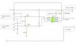
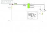
Hey guys, im just trying to make like a traffic light system where the red led shows for 1 second and then turns off and the green led turns on for 1 second and then turns off. to do this i am using my computer using vb.net (that code is working)

This is my code:
main:
serin 3, n2400, b0
select b0
case "l"
high 1
pause 1000
low 1
pause 1000
case "r"
high 2
pause 1000
low 2
pause 1000
endselect
goto main

my problem is the leds do not turn off, they stay constantly on
 

geoff07

Senior Member
It is a bit hard to comment, not knowing the circuit or the input stream.

I would add some test code to
a) confirm that the leds can be toggled at all - put something to do this before the loop so it runs at startup
b) add some code to check that the b0 input is what you expect
c) replace 'main:' with DO and 'goto main' with LOOP. It won't affect this issue but it will stop you being tempted to have other gotos that target main, and thus making the code harder to follow as it gets more complex. Look up Edsger Dijkstra if you want to know more about good code design! He didn't like BASIC much, but in his time the essential constructs like Case and do/while etc weren't in the language.

Probably by the time you have done this you will have a much better idea of what is wrong.
 

inglewoodpete

Senior Member
I think the problem is that you are not receiving the character that you are expecting.

Try this code to test that the LEDs flash:
Code:
main:
	If b0 = "l" Then
		b0 = "r"
	Else
		b0 = "l"
	EndIf
	'
	select case b0
	case "l"
		high 1
		pause 1000
		low 1
		pause 1000
	case "r" 
		high 2
		pause 1000
		low 2
		pause 1000
	endselect
	goto main
And this to see what data you are receiving:
Code:
	#Terminal 4800	'or 9600, depending on PICAXE chip
main:
	serin 3, n2400, b0
	SerTxd("Byte value = ", #b0, ", Character is: ", b0, CR, LF)
	select b0
	case "l"
		high 1
		pause 1000
		low 1
		pause 1000
	case "r" 
		high 2
		pause 1000
		low 2
		pause 1000
	endselect
	goto main
 

Alex3k

Member
I have attached the circuit diagram. sorry about the lack of the LED symbols, i am not at school and therefore had to use trusty paint :D


I tried your code, everything works, i am reciving the correct things but they do not just turn off, they stay on.
 

Attachments

geoff07

Senior Member
There don't seem to be any series resistors in line with the leds, if I read it right. Though I'm unclear about what seems to be the led connected to the 220 ohms resistor. For the red and green leds, which I assume are connected to the lines that go to the right, there should be something to limit the current. Try 330 ohms if you want them bright and 1k if dim is ok or you are using a battery. I don't know what happens if you overload a Picaxe port but you may have just found out!
 

MPep

Senior Member
Doesn't look like a PAINT drawing but rather a YENKA one. The circuit is very difficult to follow.
You haven't specified a PICAXE type. I simulated using a 08M.
In its most basic form see my attached schemtic. Hope it helps.

It doesn't make sense as to why the LED would remain ON, as the code is very clear about the course of action.
IWP's second code would be the one to use in order to see whatr is being received.
 

Attachments

Alex3k

Member
apologizes, i meant that it was originally done in yenka however i do not have it at home therefore i adjusted it using paint. A bit of a development, when i press the button once it just turns on, when i press it again it turns off and then back on and stays on. I will test the second bit of code when i return home (im at work at the moment)
 

MPep

Senior Member
In that case I suspect that you have the LEDs tied to +ve, not -ve. Try adjusting the code to be LOW first, then switching HIGH. Does that work?
 
Top