Can math solve the question of how many bits of resolution are in use here?

wapo54001

Senior Member
I’m just curious, and I don’t have the math skills to figure this out for myself, hoping someone can answer the question without difficulty.

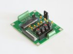
I’ve been using this circuit for years on 28X2s having created it to precisely control the resistance of a very non-linear LDR over a resistance range of 40R to 10K with 10K requiring vanishingly small amounts of current, but now I’d like to know:

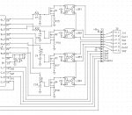
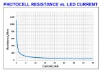
I use two overlapping 10-bit ADC10 ranges, one being 0-5V (supply) to control up to 10mA of current and resistances from 40R to about 220R, and the second being 0~0.297V to cover the range from 220R up to 10K ohms with high resolution especially near the 10K point. But what is the effective bit resolution of the combined ranges? Is this range and resolution within the capability of a 12-bit device?

Or maybe the question doesn't make any sense?
 

Flenser

Senior Member
A 12-bit ADC will not give you the same resolution in the range 0-0.297V.

For the range 0~0.297V a 10-bit ADC gives 1023 steps of 0.00029V
For the range 0-5v a 12-bit ADC gives 4095 steps of 0.0012V, so about 1/4 the resolution.
 

bpowell

Senior Member
I can't wrap my head around your application ... can you explain what the LDR is doing, and why you're reading it with different ADC's?
 

wapo54001

Senior Member
My original interest is in hifi audio electronics. On www.diyaudio.com a guy (handle=Georgehifi) was flogging an interesting volume control using four LDR modules as the four resistive elements needed to create a stereo volume control. His approach was to buy thirty or forty LDR modules (with loose manufacturing tolerances) and select four that were closely matched and control them with a log potentiometer managing the current through the LDRs. The idea was that the audio would pass through the LDR element and have better sound quality than passing through a conventional carbon or plastic pot.

I thought that was pretty inefficient, so set out to design a Picaxe-based system that would compensate for the disparities between any four LDR modules without preselection, and make them play nicely as an accurate dual potentiometer. I'm not an engineer nor a mathematician, what I did was pure brute-force trial-and-error, but eventually created a system using the 28X2. It requires a calibration phase where the LDR resistances are measured at more than 20 points between 40 ohms and 10K ohms to determine the current required to achieve each resistance point. Then during operation I use tables and formulas to interpolate current required for resistances between the measured points for smooth continuous control. These values are stored in memory and called up with the needed interpolations during actual control of an audio signal. Someone on the diyaudio website measured the accuracy of my control and found that cross-channel volume level tracked within 0.1db which is way better than a conventional dual potentiometer.

I started to sell it but quickly realized that a) I was a better technician than a business person and b) I did it for fun, not profit, and selling was no fun, especially because my customers were almost entirely in Asia and Europe and shipping was a serious pain in the patootie. Thus, today I still have fifteen or twenty full sets of the LDR control board, IR/encoder control board, OLED display, etc sitting in a box somewhere taking space and, at pushing eighty, I have no desire to do anything with them! One of the great follys of my life.

Anyway, I'll attach a graph of the resistance vs current graph of the LDR (NSL-32SR2) which will give you an idea of the great difficulty in controlling the device with a 10-bit Picaxe, and a schematic of the control circuit, and a picture of the LDR control board.
LDR controller reduced.jpgnsl circuit.jpgnsl32sr2.jpg
 

wapo54001

Senior Member
So, here's an explanation of my method (a reply I posted on diyaudio to a question from someone who had tried and failed to do the same thing):

I do not use pwm or any stepped current or voltage. Instead, my power supply is infinitely variable. I use feedback (better than 12-bit) to measure the current passing through the circuit and then direct pulses of power to the gate of a mosfet to control current through the mosfet which controls current through the LDR.

The duration of the pulse can be varied between continuous and as short as 60 micro seconds (I think I got this value from hippy back in the day a decade ago). That pulse is passed through a 1 megohm resistor to the high impedance gate of the mosfet which is loaded with a 1uF tantalum capacitor.

The pulse is tri-state -- it can be above or below the gate capacitor state, or floating (causing no change) depending on whether the gate is where it needs to be or which direction I need to drive it.

The result is extremely accurate control of the current in the circuit between 10 milliamps and virtually unmeasureable. The power delivered in 60 micro seconds across a 1 megohm resistor with a few volts differential is vanishingly small and thus I can control the mosfet gate to very tight tolerance.
 

wapo54001

Senior Member
Thanks. The need to do this is why I got into Picaxe. Wound up with a complete preamp management system all based on Picaxe chips. Not shown - the input selector board.

9427249_orig.jpg
 

julianE

Senior Member
it's amusing the trouble we go through to get nearly perfect sound. the sad part, out of thousands of recordings that i own there are at most a couple dozen that both have a great performance and are well recorded.
 

wapo54001

Senior Member
For me, it was the technical challenge of creating a better mousetrap back in the day when these chips were a whole new world . . .
 
Top