Brownout / reset mystery

bfgstew

Senior Member
I shall apologise first off for a lack of detail as I am at work and unable to offer photo's of circuit.

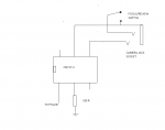
My problem is on an optocoupler circuit to fire my camera, it works fine with just the camera on, and OK when I add my flashgun onto the camera, the problem arises when I add my 90mm home made ringflash onto the camera, (the ringflash is fired by my flashgun and works perfectly OK, when off the circuit) now what happens is when the camera is triggered it causes my circuit to reset? Now the optocoupler is a CNY17-3, input onto pin1, ground on pin 2 with a 330 ohm resistor added, output is on pins 4 and 5, base is left floating, I have checked, double checked and even used a MEGA to test the tracks on the OUTPUT side of the circuit, all is fine, no dubious joints or tracks, so how can an isolated circuit cause my circuit to brownout / reset?
It know must be due to something on the ringflash, is it too much current, to higher voltage and causing a spike or transient voltage to fly around, and if so how can this be cured please.
As I said at the start, sorry for lack of detailed info, but this is so frustrating as I am so close to completing this project.

Edit, running 40X2 chip, off 12v wall-wart unit and voltage is regulated to 5v as per Rev-Ed directions, doesn't do this during any other operation in program, just when camera is fired with ringflash attached.
 

g6ejd

Senior Member
EMP - electromagnetic pulse or EMC conduction problems, a well know problem.

However, I suspect some coupling between grounds, can you run the camera (or are you) off batteries to eliminate a ground coupling issue.

Do you have de-coupling capacitors adjacent to the 40X2 chip, a few 0.01uF and say 1 x 10uF in close proximity to the 40X device are need as a minimum.
 

bfgstew

Senior Member
EMP did cross my mind, but how can that be supressed?

40X2 is decoupled using 10uf as close as possible to the chip.

Running off 4AA batteries is going to be an option, but not tried or tested yet.
 

bfgstew

Senior Member
running 40X2 chip, off 12v wall-wart unit and voltage is regulated to 5v as per Rev-Ed directions, doesn't do this during any other operation in program, just when camera is fired with ringflash attached.
As stated in first post, everything else works perfectly, all tracks, joints, etc check out so it's just this part of the circuit where the fault is generated, I only have segmented schematics for this project until it is completed then schematic will be drawn up completely.
EMP, sounds the most feasible explanation and if so, how can this be dealt with?
 

bfgstew

Senior Member
OK reading a bit more into this and found it rather interesting. Wiki covers it and a solution, so in theory a ferrite bead choke may cure the fault? I know it may not be as simple as that but am I on the right path?
 

bfgstew

Senior Member
Sorry all I do have a 100nf cap fitted, not a 10uf one..........:rolleyes:
Would better decoupling be a better starting point and if so, what size cap?
Will give the battery pack a try later as well.
 

Buzby

Senior Member
The Nikon, if I recall is 27v, well that's what I have measured off the hotshoe.
The trigger might be 27v, but the xenon tube is more like 450v. That's a *big* spike induced in any wires in the vicinity.

Maybe try a 0.1uF from pin 1 of the opto to ground.
 

SAborn

Senior Member
I would suggest using 2 power supplies, as the two circuits are opto isolated and there is no need to have a common ground between picaxe and trigger circuit, its the main reason we use optocouplers is to isolate circuits from each other to solve these sorts of problems.
 

bfgstew

Senior Member
OK, tried with 0.22uf, 0.47uf ceramic caps, no different, also tried with 0.1uf electrolitic cap, no difference.

I may disconnect opto from copper tracks and add wires to it so circuit is seperate from board as some tracks are fairly close, see how that goes?
 

Dippy

Moderator
Can you post a schematic that accurately represents circuit. Including exact values.
You may spot something while you are preparing it.


You say you've decouple/bypass caps; how close to PICAXE?

How have you connected PICAXE reset pin?
Some circuits can benefit from a little cap here - see M'chip data sheets for details.

Is it a nice neat tight layout or hairy old veroboard with gert long wires and tracks all over?
Are the grounds definitely separate?
How close is PICAXE to flash?
Are there any light sensitive devices on PICAXE circuit?
Have your tried shielding of PICAXE section (including wires which act like little antennae)?


This is where a 'scope can save hours.... Christmas will soon be here ;)
 

rossko57

Senior Member
the problem arises when I add my 90mm home made ringflash onto the camera, (the ringflash is fired by my flashgun and works perfectly OK, when off the circuit)
Can you clarify a bit, does the ringflash actually fire when the trigger event occurs that 'resets' the picaxe? How does the commercial flashgun fire your ring, a wired trigger to independant driver, or dangly kV wires direct to the tube, or?
Howdo you know the picaxe is reset? Can you make it do the same thing if you fire the flash(es) independantly, maybe trying with and without the wired connection, or with varying seperation?
 

bfgstew

Senior Member
Did you try a cap from pin 1 of the opto to ground ?
I did Buzby

Can you post a schematic that accurately represents circuit. Including exact values.
You may spot something while you are preparing it.


You say you've decouple/bypass caps; how close to PICAXE?

How have you connected PICAXE reset pin?
Some circuits can benefit from a little cap here - see M'chip data sheets for details.

Is it a nice neat tight layout or hairy old veroboard with gert long wires and tracks all over?
Are the grounds definitely separate?
How close is PICAXE to flash?
Are there any light sensitive devices on PICAXE circuit?
Have your tried shielding of PICAXE section (including wires which act like little antennae)?


This is where a 'scope can save hours.... Christmas will soon be here
Schematic is shown in earlier post, cap is as close to chip as possible, reset is as per Rev-Ed directive, it is a tidy PCB layout and tracks are about a 1mm apart, flash a few feet away and no light sensitive bits on circuit, shielding is going to be next bit I think! I do have a DpScope but not sure how to test for high voltages with it?

Can you clarify a bit, does the ringflash actually fire when the trigger event occurs that 'resets' the picaxe? How does the commercial flashgun fire your ring, a wired trigger to independant driver, or dangly kV wires direct to the tube, or?
Howdo you know the picaxe is reset? Can you make it do the same thing if you fire the flash(es) independantly, maybe trying with and without the wired connection, or with varying seperation?
Flash fires and as soon as it does system goes into 'reset' and back to its main menu, flash id fired by the speed light through an umbilical cord, only resets when ringflash is on and fires, doesn't do it with just the speedlight on and firing.
 

Dippy

Moderator
"Schematic is shown in earlier post"
- I must have missed something. All I can see is a sketch of an opto + jack..... is there a full one somewhere?


"I do have a DpScope but not sure how to test for high voltages with it?"
- you're not necessarily testing HV. You're testing for spikes/dips on power and signal lines.
I don't know what a 'DpScope' is. Is it fast enough for MHz spikes?

Spikes on I/O, reset or power can upset micros.
 

bfgstew

Senior Member
Sorry Dippy not got round to doing full schematic, am in the process of doing it, but time is against me most days and only get an hour here and there to do anything on it.

DpScope, by Womai
 

bfgstew

Senior Member
I did some checks with my scope but it was a difficult and time consuming exercise, so I decided to solder lengths of wire from the opto output pins to the camera socket and switch and it seems to have worked, this was just a temporary solution to test the theory, now it looks like it works do I use screened cable to remove any chance of stray EMC in the enclosure? If so how do you terminate the screens at either end of the cable?
 

SAborn

Senior Member
Good to see you finally isolated each circuit on the opto coupler, as with a isolated controlled circuit there should be no interference with one or the other, unless its RF noise.

One would expect you want a nice soft flexible cable, so i would suggest microphone cable, as it has a outer screen and a inner single core.
Even the lead off an old mouse or usb cable will do as they normally have a screen wire,

Just use the screen as Gnd and unused wires also connected to ground.

A good exercise to do that often shows the EMF in a circuit, is to place a Neon globe across the circuit power wires to the flash ring, a neon globe takes around 100V to fire the globe, and most times you will see the neon flash if the EMF is not suppressed.

I would also suggest you place a snubber diode across the supply rails at the flash ring itself, Because if there is high voltage EMF the opto transistor may be over stressed, that might result in failure, and EMF is better snubbed at the flash ring circuit before it reaches the opto.

If you had given a full schematic much earlier than you would have likely saved a lot of test time, but test time is also good, as it makes us think more, learn, and develop new skills in electronics.
 

bfgstew

Senior Member
All's well, that ends well, so they say!

After a few alterations it was still causing my unit to reset, now at this point a pair of size 15 boots are ready to stomp this thing, off into the garden for a brew, relax and calm down. Went over it again, double checking the PCB layout draft and noticed 1 track went under the CNY17-3, this was for the focus/review switch (totally forot it was there), simply removed the track and re-routed with a length of wire and now success.
Set up my macro rig to test it and my camera battery is flat, goes to show, when the Gods are against you, they are against you!

Thanks everyone for your help, guidance and patience.

Stewart

PS nearly completed schematic, when I have I will post it for some serious critique!
 

Dippy

Moderator
Good result.
So, it wasn't the cable?
Are you sure this is the answer?
You can't blame not-getting-things-ready on the Gods* old chap - See you soon ;)

*Unless you're talking about Sloblock , the God of forgetting to put the charger on.
 

bfgstew

Senior Member
So, it wasn't the cable?
More the tracks than the cable, it didn't work with the track under the opto, it worked after the track was removed, something to remember for future projects/designs!

Unless you're talking about Sloblock , the God of forgetting to put the charger on.
LMFAO
 
Top