Brownout Circuit help

leesheph

New Member
Hi there

This is my first post so please, be gentle!

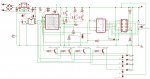
First off some info on the circuit, it is a PICAXE18X based timer project using a DS1307 RTC for time keeping and a 74LS164N to interface a HD44780 LCD using Hippys code and circuit design (Thanks Hippy!)
Outputs from the PICAXE switch 3, 5V relays, thru BC517 Transistors. The unit is powered from mains thru a bridge, smoothing caps etc then into a 7805 reg.

My problem is that as this is my first PICAXE project I have overlooked the issue of brownouts, particularly the DS1307, this seems the most sensitive to low supply voltage. Is there a simple circuit I could retro fit to my already built design?

I was thinking that I could feed all the chips power thru a transistor which was turned on from a zener diode fed thru a potential divider from the output of the 7805, does this sound feasible? do you guys have any 'standard' ways to deal with brownout's?

all help MUCH appreciated.

Regards

Lee Shephard
 

BCJKiwi

Senior Member
Not sure if this is the right answer but the DS1307 is designed to utilise a coin cell type battery backup to keep it's clock running when power is off. Do you have a backup battery installed? If not, fitting one should sort the DS1307 issue.
 

Dippy

Moderator
I must admit I ddn't understand your paragraph about transistors and zeners etc...

As BCJ says about battery backup for DS1307, that really should be 'standard' in your design.

I guess for brownout protection for your circuit then there are a few options:
a) For tiny brownouts a healthy amount of capacitance in your regulator circuit would help.
b) If it's occasional brownouts the old battery pack + diode may help.
c) For regular long brownouts a rechargeable + trickle + diode would be better.

Probably other methods too depndingon your overall circuit design and loading.

Watch this space...
 

leesheph

New Member
guys, thanks for your replies. I should have specified that I am already using a coin cell on the DS1307...the problem is that after a small brown out the chip appears to 'hang' and I only get junk back from it...is there a way to 'reset' the DS1307?

I also have 470uF before and after the reg plus decoupling caps on all chips and reg legs.
 
Last edited:

hippy

Ex-Staff (retired)
What sort of brownouts are you seeing ? How are you sure it is a brownout causing the problem ?
 

leesheph

New Member
Hi Hippy

The timer switches 3 mains relays and when I put a large (10amps resistive) load on them it droops the mains supply a little (I think) and as I was using a 6vac transformer it would drop just enough so that the reg would not work properly, I have already upgraded the tran to a 9vac to help this but it got me thinking as to how the circuit would behave in a 'real' brownout...

I want to be able as far as possible leave the timer unattanended and therefore it would need to cope gracefully with mains fluctuations.

thanks everyone for your thoughts
 

Dippy

Moderator
"I think".... oh.
Have you actually done any measurements?
I doubt the small 'droop' on your mains side would be seen as a brownout post-transformer unless your wiring is terrible.
If you're having problems it sounds more like little spikes are getting through.

Sadly, without seeing your schematic or pile of wires it's a bit of a guessing game.

Maybe someone could post a little schematic for a basic battery backup?
 

leesheph

New Member
Thanks for the circuit Ibenson, but I am not convinced that I need to go that far yet.

This morning I did some tests as I should have done before posting! :-\

I measured the circuit at 3 points, transformer secondary, post diode bridge and reg output first with my current 6v/6va transformer and then a new 9v/6va transformer. Here are the results:


6V 6VA Transformer

No load, no relays on
Tran Output (VAC) 7.5
Post Bridge(VDC) 8.23
Post 7805(VDC) 5.05

No load, 3 relays on
Tran Output (VAC) 7.1
Post Bridge(VDC) 6.9
Post 7805(VDC) 4.8

10A load, 3 relays on
Tran Output (VAC) 7.02
Post Bridge(VDC) 6.8
Post 7805(VDC) 4.7


9V 6VA Transformer

No load, no relays on
Tran Output (VAC) 11.12
Post Bridge(VDC) 12.9
Post 7805(VDC) 5.05

No load, 3 relays on
Tran Output (VAC) 9.95
Post Bridge(VDC) 10.3
Post 7805(VDC) 5.03

10A load, 3 relays on
Tran Output (VAC) 9.72
Post Bridge(VDC) 10.0
Post 7805(VDC) 5.02


as you can see the reg input voltage gets dangerously low on the 6v transformer but is fine on the 9v...this has fixed the problem when it is switching a heavy load but does not answer my original question...what happens in a real brownout and how to recover from it? I simulated a quick brownout buy swicthing the mains socket very fast on and off and it worked fine until i did it VERY fast, then the whole thing froze.

Next I increased the smoothing caps to 2 x 1000uf and this just made the problem worse (ie a slower switch would cause a freeze)

Any ideas? I can post a schem if it would help.

Thanks for you time

Lee
 
Last edited:

BCJKiwi

Senior Member
Presumably the "Post Bridge VDC" is not smoothed else the 6V 6VA Transformer giving 6.8v should be high enough for the the 7805 to work with. This is incorrect - see below - 7 to 7.5V required to give stable regulated 5V with the LM7805

Smoothing caps at 1000uF (presumably one each side of the 7805) are overkill.

I am always puzzled by the use of giant caps on the output of the 7805 - the specs sheets don't call for anything other than the high frequency filter cap of 0.1uF on the output and all tests I've done show big caps on the output don't achieve anything (unless you have big inrush currents to some device off the 5v rail).
The 0.33uF and 0.1uF caps (tantalum or electrolytic) specified in the data sheets must be installed as well as the big tanks - without them the 7805 won't be stable!

Perhaps a circuit would help us understand what is going on as it does not quite seem to make sense so far.
 
Last edited:

hippy

Ex-Staff (retired)
A 6V transformer ... I'm not as convinced as BCJKiwi that 6.8V should be enough for the 7805 to work with, although it varies with manufacturer.

The simple solution seems to be to use a higher voltage transformer. The relays are 5V and presumable connect to the 7805 regulated rail so I don't see any problem with doing that.
 

leesheph

New Member
Hi BCJ

I have attached a schematic of my circuit the only things it does not show are the transformer and the relays.

I should then remove the 1000uf caps each side of the reg and replace with one 470uf after the bridge, is this correct?

I have 0.1uf caps each side of the reg is this ok or should I change the input side to 0.33uf?

many thanks

Lee


Attachments

leesheph

New Member
A 6V transformer ... I'm not as convinced as BCJKiwi that 6.8V should be enough for the 7805 to work with, although it varies with manufacturer.

The simple solution seems to be to use a higher voltage transformer. The relays are 5V and presumable connect to the 7805 regulated rail so I don't see any problem with doing that.
Hi Hippy

yes, as my test showed all was fine with a 9v transformer instead of a 6v...but I still have the problem of how to deal with a real brownout...ie how to stop the picaxe and ds1307 freezing up after a very short power outage..
 

Dippy

Moderator
Lee's testing is an example of transformer regulation and also the dropout of those dinosaur 7805 regulators. 6V transformers are available in all sorts of regulation values usually given as a percentage and reflects how the AC on secondary varies with load.

But 'brownout' on mains means a dip not a complete loss like switching it off/on.

When you switch things off/on quickly you can also introduce a surge/spike. These spikes will go 'straight through' your avergae regulator, so you aren't really simulating a brownout.

Whilst I agree with BCJ that monster cacpitors are an overkill but careful physical placment of suitable caps (type and size) can reduce these spikes getting through. And also if they are placed in a position in your circuit where current-dumps are likely then it can prevent processor hang-ups.

So, not only would your circuit schematic be handy but also your layout. All these things can affect performance. Theory is fine, but real life.....
 

hippy

Ex-Staff (retired)
I still have the problem of how to deal with a real brownout...ie how to stop the picaxe and ds1307 freezing up after a very short power outage..
Unfortunately there's no easy answer to that. Largish reservoir capacitors usually hold up the supply but at some point there's going to a problem; voltage dipping too low, surges and spikes at turn-on and turn off.

To know what's needed to fix the problem means having to know exactly what's causing the problem, it's "failure mode", and exactly what effect it is having. Although it's related to switching the supply it may not be brown-out but on the contrary related to spikes or surges when power is re-applied. With the back-EMF diodes on the relays, and a collapsing power supply, who knows what that might dump into the 7805. Maybe a diode to dump current from 7805 output to input as they don't like to be reverse biased.

As it's an 18 it is possible to add a brown-out detector to force reset and hold it there until everything is stable and a watchdog can force a reset if the PICAXE appears to have died. To actually solve the problem though you have to know what it is you are trying to fix, or just live with it.

Check how you've actually got your supply wired to your PICAXE. Not sure where the PICAXE device "U1" diagram came from but it shows VDD(+V) to 0V and VSS(0V) to +5V, although the pin numbers appear to be correct, so it may just be a mis-labelled diagram, or is it mis-labelled pin numbers? Best to actually check what is on the board and update the library so it's consistent and correct.
 

BCJKiwi

Senior Member
@Hippy,
My comment re the 6V trans was trying to say that if there really was smoothed 6.8V at the input to the 7805 then it should be OK. i.e. 6.8V is more than 1.5V above 5V. This is incorrect - see below - 7 to 7.5V required to give stable regulated 5V with the LM7805

@leesheph
Re your question on the caps.
It seems that as the relay coils are on the same 5V rail as the PICAXE etc, then you might expect some interference and higher (9V Trans) supply and larger caps would certainly help there.

The bridge needs decent caps on the output to take the ripple out of the rectified AC. The 0.33uF and 0.1uF caps are still required. A larger cap on the supply rail to act as a reservoir for the relay coils supply should also be considered.
So one 1000uF cap right across the bridge rectifier and the other close to the relay coils that would be the best positioning for them. The 0.33 and 0.1 should be right on the either side of the 7805.

It seems the discussion is about two different issues,
1. Insufficieint supply capacity causing unstable normal operation - fixed by 9V Trans / bigger Caps
2. How to deal with an unstable mains supply (Brownout). - If you don't have a UPS then you need a battery backup as suggested by Dippy and supplied by Ibenson.
 
Last edited:

hippy

Ex-Staff (retired)
@Hippy,
My comment re the 6V trans was trying to say that if there really was smoothed 6.8V at the input to the 7805 then it should be OK. i.e. 6.8V is more than 1.5V above 5V
The first 7805 datasheet I pulled from t'internet at random needed 2V headroom, and I've usually worked on 3V as a comfortable margin regardless of manufacturer.
 

leesheph

New Member
Thanks everyone! very usefull comments.

I think BCJ's explaination of the problem(s) is correct, this first one was fixed by a bigger transformer, but the second remains..the problem of mains spikes/back emf from relay coils and a real brownout.

the realys are mounted off the main board so are you saying I should move the 1000uf cap closer? also would a MOV across the output of the 7805 stop any spikes or should I just go with the diode?

I will upload a board layout on Monday as I am at home now.

Hippy, yes that U1 diagram confused me too, I use a Library from the Eagle website which may be out of date, i'll check on Monday!

Once again, thanks everyone.

Lee
 

Dippy

Moderator
Personally, I'd be tempted to put a 220uF cap at the point where your relay coil Vsupply is taken on-track and also return the back-emf diodes Kathode to that same point. That is physically the place where highs and lows will appear on your circuit track. Where I have had similar issues I've chosen the slightly more xpensive Low-Z type cap with success.

I'd have a VDR (or similar MOV) on the mains IN and a mains rated R/C suppressor as well (100R+0.1uF I think). This method completely got rid of problems I was having with fluorescent light switching interfering with a circuit I did yonks ago. You really need to attenuate the spikes 'before' they get into the transformer.

A R/C suppressor ('arc' suppressor) accross relay o/ps may be a idea too. I would add (not rplace) 22uF lo-Z cap to your 100nF you have across the PICAXE +V/Gnd as physically close as possible.

On some circuits in the past, where big pulses were apparent on my +vsupply rail, I used a mild R/C filter for the V+ of the processor too.

And make sure your wiring is as robust as possible. Any weediness will result in in-circuit dips whe there are transients kicking about (e.g. relays being switched). Obvioulsy you are keeping the mains as far away as possible from where nasties can be induced into Low V side??

Genuine Brownouts can be sorted with the suggestions made previously.

PS. DO read up about tranformer regulation too... it can save a lot of head-scratching in future and save your wallet and time too. So many people don't even consider it , and think a transformer is a transformer is a transformer.
 
Last edited:

BCJKiwi

Senior Member
@ Hippy,
Yes you are correct (again!). Checked a couple of data sheets and 2V / max 2.5V is the specified drop out voltage.

Often use the LM2940 as it has all sorts of additional functionality & is designed for automotive use and is more robust. The LM2940 is an "LDO" unit with 0.5V / Max 1.0V dropout.

@leesheph
As advised previously by Dippy;
tiny brownouts = more capacitors,
real brownouts = backup supply
Do you really need to cover for real brownouts? After all, the rest of the mains supplied system (with 10 amp loads) would fail/be unstable anyway so maybe a full restart when power is back to normal is the best thing anyway - only you know enough about the system to decide.

The other thing I've just noticed in the LM7805 Data sheet is the graph which shows the highest current capacity (2.3A) is achieved with an input/output differential of 5.5 to 7.5Volts while over the same range the quiescent current increases by about .25 of a mA.
This would suggest (if I am interpreting the graphs correctly) that it may be best to supply a 5 V regulator from a 12V supply.
 
Last edited:

inglewoodpete

Senior Member
Lee, You reported the original problem:
guys, thanks for your replies. I should have specified that I am already using a coin cell on the DS1307...the problem is that after a small brown out the chip appears to 'hang' and I only get junk back from it...is there a way to 'reset' the DS1307?
The discussion appears to be off with other topics.

With a 3v battery connected, the DS1307 should be 'very stable', regardless of what else may be happening around it. Eg a power failure or even a brownout should not affect the DS1307 chip. Rebooting the PICAXE should be all that is required if there are power problems. The DS1307 should not 'hang' unless you have a wiring problem around it.
 

Ralpht

New Member
As Inglewoodpete infered, it is very unlikely that the DS1307 would hang.

More than likely, the picaxe itself "hangs" and currupts the data from the '1307.

The best alternative would be a watchdog that resets the picaxe if it goes off into it's own little world.

The easiest way to do that is to use one output of the picaxe to produce very regular pulses to a "watchdog" be it a '555 or similar chip. If it does not recieve its regular pulse from the picaxe it times out and forces a reset on the picaxe.

I think that a perusal of the forums will show many different ways of actually doing this.
 

leesheph

New Member
WOW! thanks everyone, I have learn't a lot reading those last post from you all.

from what has been said my feeling is that the hang (which is probably the 18X and not the ds1307) is actually spikes etc finding there way into circuit.

I am going to try the following based on you recomendations:

1. Add 22uf to the 100nF close to the PICAXE.
2. Add MOV and R+C filter network to the mains side of the transformer.
3. Physically relocate the PCB further away from mains components.

Would you alter anything else?

Thanks

Lee
 

Dippy

Moderator
It is difficult to say really as suppression of spikes etc can be tricky and is sometims a bit of a 'black art'. Sometimes it can be something trivial like earthing/grounding am enclosure.

Many people have subtly different methods of sorting it. But try those things you've mentioned to start with and you will probably get a list of 'My Favourite Suppressor' from different contributors.

Just remember to get the properly rated components and keep lead lengths as short and safe as possible. You'll get it sorted don't worry.

(PS. But please remember that all the suggestions in this thread are suggestions - we haven't got your circuit-board sitting in front of us)
 
Last edited:

leesheph

New Member
Just reporting back, I did as above ie. added a 22uf to the 100nf cap on the PICAXE, added MOV and RC filter on mains side of transformer and moved all mains parts and cables as far away from the pcb as possible (phew) and so far its been PERFECT :)

Thanks SO much for all the help, it is much appreciated and I will be including the tips on pcb layout into my next version of the board.

Best regards

Lee
 

Dippy

Moderator
Excellent. The next time this sort of thing crops up with others then you can advise them of your findings.
 
Top