Minifig666
Senior Member
I have been looking forward to using my etching equip for a while now but before I go and waste a whole batch.
Anyway on with my board:
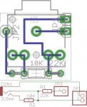
The board I have designed is my own implementation of the AXE029 breadboard adaptor which is compatible with the 08,14, and 20 chips. I use the 08M allot so this one would be more convenient for me. The idea is that it straddles the chip and connects to the SERI/O pins and 0V as used many chips. I wanted it to be very small so the resistors are piggybacked behind the connector and the header pins are tucked under the connector. I just have a few questions. What is the best way to connect the header pins to the bottom of the board (it's single sided) and is my board correctly laid out correctly? Also as seen in the Arduino system how do you have both male and female header pins at the same point?
Anyway on with my board:
The board I have designed is my own implementation of the AXE029 breadboard adaptor which is compatible with the 08,14, and 20 chips. I use the 08M allot so this one would be more convenient for me. The idea is that it straddles the chip and connects to the SERI/O pins and 0V as used many chips. I wanted it to be very small so the resistors are piggybacked behind the connector and the header pins are tucked under the connector. I just have a few questions. What is the best way to connect the header pins to the bottom of the board (it's single sided) and is my board correctly laid out correctly? Also as seen in the Arduino system how do you have both male and female header pins at the same point?
Attachments
-
 62.1 KB Views: 69