This post is intended to assist others who may be struggling with ThingM’s "BlinkM" or “MaxM” using I2C. This is specifically for those, who like me, are new to Picaxe, I2C, left-shifted environments, etc.
This information is all in the Picaxe docs, but it isn’t spelled out in reference to this device.
Also, I wanted to give something back…basic as this all might be.
Comments welcome.
All links are found at the bottom of this post.
In brief, the MaxM is a programmable 445,000 mcd RGB LED cluster, making it a handy and compact holiday lighting accessory. It is also geared toward the Arduino. So some code translation has been needed.
In order to control two MaxMs on the same I2C bus, one of the units needed to be assigned an address different from the default 0x09. This is read by Picaxe as $12. Somewhere in the programming, the addressing was messed up and I could no longer “talk to” the 2nd MaxM unit.
The MaxM documentation provides a means to assign an address even if the existing HW address is not known. Placing only one MaxM unit on the I2C bus, a “General Call” is issued. The Arduino examples refer to the broadcast address as “0x00”. But using $00 on the 20x2 didn’t work. Neither did %00000000, or anything else over the past two days. ThingM’s doc refers to “left-shifted” environments which I now realize is the Picaxe environment.
The Picaxe docs and this paragraph from:
http://www.best-microcontroller-projects.com/i2c-tutorial.html
……“connected the dots” for me.
It was the “W”.
Even though I am using a 20x2, I went the simple route piecing together other’s code examples. Just to get this to work.
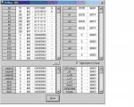
Reading the firmware (b0 and b1) confirms, the success of the address change (attachment).
BTW, the MaxM doc is wrong in that it specifies a lower case “z” on page 15 of it’s documentation –format section. Using the corresponding command byte spec (0x5a) and the PE’s ASCII table, the correct character should be an upper case “Z” (or $5a). Another 5 hours chasing moonbeams.
Placing various addresses in the M/S Windows calculator (Scientific mode) helped my understanding of Hex, Decimal, Binary....
I learned a lot here and hope this assists others who may just be starting out.
Thanks,
Terry
Previous Forum discussions "General Call".
I²C-bus specification, Version 3.0 (Rev. 03 - 19 June 2007
http://www.nxp.com/documents/user_manual/UM10204.pdf Pg 19
ThingM
http://thingm.com/products/blinkm-maxm.html
This information is all in the Picaxe docs, but it isn’t spelled out in reference to this device.
Also, I wanted to give something back…basic as this all might be.
Comments welcome.
All links are found at the bottom of this post.
In brief, the MaxM is a programmable 445,000 mcd RGB LED cluster, making it a handy and compact holiday lighting accessory. It is also geared toward the Arduino. So some code translation has been needed.
In order to control two MaxMs on the same I2C bus, one of the units needed to be assigned an address different from the default 0x09. This is read by Picaxe as $12. Somewhere in the programming, the addressing was messed up and I could no longer “talk to” the 2nd MaxM unit.
The MaxM documentation provides a means to assign an address even if the existing HW address is not known. Placing only one MaxM unit on the I2C bus, a “General Call” is issued. The Arduino examples refer to the broadcast address as “0x00”. But using $00 on the 20x2 didn’t work. Neither did %00000000, or anything else over the past two days. ThingM’s doc refers to “left-shifted” environments which I now realize is the Picaxe environment.
The Picaxe docs and this paragraph from:
http://www.best-microcontroller-projects.com/i2c-tutorial.html
……“connected the dots” for me.
It was the “W”.
General call
The general call address is a reserved address which when output by the bus master should address all devices which should respond with an acknowledge. Its value is 0000000 (7 bits) and written by the master 0000000W. If a device does not need data from the general call it does not need to respond to it.
The general call address is a reserved address which when output by the bus master should address all devices which should respond with an acknowledge. Its value is 0000000 (7 bits) and written by the master 0000000W. If a device does not need data from the general call it does not need to respond to it.
Even though I am using a 20x2, I went the simple route piecing together other’s code examples. Just to get this to work.
Code:
#Picaxe 20x2

MAIN:

I2cslave %0000000[COLOR="Red"][B]1[/B][/COLOR], I2cslow, I2cbyte	‘Set the broadcast address for the I2C bus
	Pause 100

WriteI2c 0,("A",$12,$d0,$0d,$12)	‘Assign the sole I2C device on the bus an address of $12.
                                       `After programming control of the unit is thru address $24
        Pause 100
End
Code:
#Picaxe 20x2

MAIN:

I2cslave $24, I2cslow, I2cbyte			`Set the slave address
	Pause 100

Writei2c 0,("Z")				‘Send the MaxM “Read Firmware” command
	Pause 100

Readi2c 0,(b0,b1,b2,b3,b4,b5,b6,b7)		‘Read the populated variable in Debug
	Pause 100

Debug b0
	Pause 500

Goto Main
BTW, the MaxM doc is wrong in that it specifies a lower case “z” on page 15 of it’s documentation –format section. Using the corresponding command byte spec (0x5a) and the PE’s ASCII table, the correct character should be an upper case “Z” (or $5a). Another 5 hours chasing moonbeams.
Placing various addresses in the M/S Windows calculator (Scientific mode) helped my understanding of Hex, Decimal, Binary....
I learned a lot here and hope this assists others who may just be starting out.
Thanks,
Terry
Previous Forum discussions "General Call".
http://www.picaxeforum.co.uk/showthread.php?t=12321&highlight="general+call"
http://www.picaxeforum.co.uk/showthread.php?t=2476&highlight="general+call"+i2c
http://www.picaxeforum.co.uk/showthread.php?t=2476&highlight="general+call"+i2c
I²C-bus specification, Version 3.0 (Rev. 03 - 19 June 2007
http://www.nxp.com/documents/user_manual/UM10204.pdf Pg 19
ThingM
http://thingm.com/products/blinkm-maxm.html
Attachments
-
 75.6 KB Views: 24