Bipolar stepper motor

Denzel

Senior Member
I have been tring to get a stepper motor going from a circuit out of David Lincoln's "Experiments in mechatronics using the picaxe controllers"

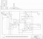
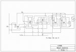
The circuit uses an L293d to supply the two coils with 12v

I have made the circuit up exact to the diagram and the code is exactly the same but the stepper just seems to judder, get hot, and not really rotate consistently.

Is there a particular order the four wires from the stepper are meant to go high

heres the code supplied with the schematic
ca (pin 1) and nca (pin 0) are two wires from the same coil and cb (pin 4) and ncb (pin 2) are from the other coil
----------------------------------------------

symbol ca = 1
symbol nca = 0
symbol cB = 4
symbol ncb = 2
symbol delay = 50
symbol counter = b0

Main:
for counter = 1 to 50 'forward
gosub an
gosub ab
gosub nb
gosub nn
next counter

pause 500

for counter = 1 to 50 ' backward
gosub nb
gosub ab
gosub an
gosub nn
next counter

pause 500

goto main

an:
high ca
low nca
low cb
high ncb
pause delay
return

ab:
high ca
low nca
high cb
low ncb
pause delay
return

nb:
low ca
high nca
high cb
low ncb
pause delay
return

nn:
low ca
high nca
low cb
high ncb
pause delay
return
----------------------------------------------
I have tried all the combinations (i think) of an ,ab ,nb ,nn with much the same results

Any help would be appreciated
 

manuka

Senior Member
I've just glanced at your code, which had me thinking both time durations & sequencing may be the culprit(s). Is your PSU up to it however-many steppers are power hogs!

David & I have just been discussing friendlier PICAXE driven steppers as it happens, & have considered Electronic Goldmine US$1.49 darlings ideal => http://www.goldmine-elec-products.com/prodinfo.asp?number=G14197. Amazingly they draw only 20mA each winding, so direct PICAXE output driving can be used!

Check my 2007 "pulsed" approach based around this EG stepper, and naturally feel free to pinch my ideas. Stan => http://www.picaxe.orconhosting.net.nz/stepdemo.jpg
 
Last edited:

eclectic

Moderator
Denzel,
two things that might help.

1. Manual 3, page 17.
The "step" sequence and the wiring diagram.

2. Is one of your coils wired "backwards"?

e
 

westaust55

Moderator
EG stepper motors

Regarding the EG stepper motors,

Goldmine’s website and referenced information is a bit conflicting/confusing (especially for newcomers). First states:
. . .Has 5 leads, . . . .
Then states
The stepper motor is brand new precision made with 4 pin female connector on end of 2.8"L leads.
Goldmine’s own text suggests connect the black and white wires which results in centre tap (white) connected to the end of the other quadrature winding . Their schematic looks like a form of 3 phase stepper motor but from the above would be an imbalanced 3 phase circuit. Looks very messy and non-uniform in terms of torque available per step.

So, is the white wire pre-connected to the black wire through the 4 pin connector?


From http://www.picaxe.orconhosting.net.nz/stepdemo.jpg it suggests one lead just is not used.


Goldmine’s website state:
The stepper motor features 20 steps per revolution and is perfect for miniature robots.
Yet at http://www.picaxe.orconhosting.net.nz/stepdemo.jpg it states
24 steps per revolution
Then there is no torque data so as Mycroft suggests what is it capable of doing?

For the price and current draw, I doubt that there will be significant torque to move anything too significant.
But for educational purposes just to demo that we can rotate - fair enough.
 
Last edited:

eclectic

Moderator
@Denzel.
An addition to post #4.

David Lincoln's mechatronics book seems unavailable in this part of the globe.

(I've just tried searching the local libraries' database, and Amazon.co.uk).

If it doesn't infringe copyright, could you (or anyone else),
draw out the circuit and post it?

e
 

westaust55

Moderator
Denzel ,

The L293D is rated for a maximum continuous current of 0.6A (600mA).

What are the specs for the stepper motor you are trying to use?
Can you give a web link to a datasheet?
 

tiscando

Senior Member
Manuka:
many steppers are power hogs!
Do they consume >0.6A?

Westaust55:
The L293D is rated for a maximum continuous current of 0.6A (600mA).
If your L293d, which is supposed to be a stepper motor driver, is not enough current, then, for example, try the L298n@rapidonline.com, which supports 2A continuous-DC current per channel.
I usually make my own differential (full-bridge) drivers with chunky 8A PNP TIP2955s sourcing and 8A NPN TIP3055s sinking, according to the attached diagram.
edit: if they are all NPNs (also taking away the 100R resistors on the PNP's place, and the replaced NPNs wired up correctly), then the output voltage of the (now NPN) sourcer would only equal {Vin max Vcc, minus ~1.4v} no matter how high Vcc is above Vin.
(a GIF file may be the same as a 256 colour BMP, making conversion in 'paint' very easy by choosing the file type on the 'save as' menu:))

Oh- not again:mad: picture created by ISIS was too big again, even with the smallest resolution selected, and even with the empty bits cropped off: had to do further descaling:eek:, which means inventing a new smaller template size system:rolleyes:. Why can't a portrait 200x500 picture be uploaded like a 500x200 picture? Also, why can't Gif pictures be >~38kB, just nearer to the jpg picture's max. size: 976kB!
So, I've also downloaded the raw dsn file for people to look at (so-called). On the picture, sorry for the hard-to-read typing; the font height can't go less than 0.1in to stay readable enough (smallest typing: 0.09in)
 

Attachments

Last edited:

LizzieB

Senior Member
@Denzel.
An addition to post #4.

David Lincoln's mechatronics book seems unavailable in this part of the globe.

(I've just tried searching the local libraries' database, and Amazon.co.uk).

If it doesn't infringe copyright, could you (or anyone else),
draw out the circuit and post it?

e
Is that the correct title? Usually any book new or used can be found on www.alibris.com but the only one I see there is "Programming and Customizing the Picaxe Microcontroller
by David Lincoln"
 

eclectic

Moderator
LizzieB.

Apparently, the "mechatronics" title was written several years ago.
One of the Aus/NZ Picaxers will be able to provide more info.

I own the more modern "Programming .......", which is
easily obtainable from RevEd.

e
 
Last edited:

manuka

Senior Member
Everyone hears steppers are the way to go, but actually verifying their action can be a hassle, & daunting to manage for educators with restless students,trivial budgets & zilch technician backup. Discarded & rescued steppers may abound, but most require beefy PSUs, considerable hardware support & extra wiring before "Aha!" moments arise. By starting simply, more ambitious stepper projects become easier to comprehend, & subtle tweaks in timing & sequence a breeze to trial.

The appeal of these EG steppers is hence essentially educational, although they have shown torque enough for simple loads. For further simplicity their supply is just the normal PICAXE 3 x AA = 4½ V, at which ~20mA per winding is drawn. Naturally heavy loads will push this beyond a 08M's source ratings, in which case extra hardware will be needed (NPNs etc)- by that stage learners will have hopefully got the hang of driving bipolar steppers. We've also used that extra white wire to good effect, but for initial work it can be ignored.

EXTRA: There may well be a typo with that 20/24 step - it's been 18 months since I did this. Stan
 
Last edited:

westaust55

Moderator
Manuka:
Do they consume >0.6A?
There may be more types of stepper motors with current ratings from 1 amp to 10 amps :eek:. than below 0.6 amp

But still many rating < 0.6 Amps,

this motor is 6V 0.4 Amps and 28 x 28mm + 200 steps per revolution
http://db.sanyodenki.co.jp/stepping_e/two/index.htm
but the price . . . £35.84 (Inc VAT £42.11)


MicrcoMo make some smaller motors:
Nominal Current/Ph (2 ph on) 0.15A @ 6V (75mA/winidng)
Nominal Holding Torque (2 phase on)(1) 6 mNm (0.85 oz-in) All Types
15mm diameter and 24 steps/revolution
http://www.micromo.com/uploadpk/AM_1524.pdf

this tiny motor is 20mA per winding at 6V
Nominal Current/Ph (2 ph on) 0.040A @ 6V
Nominal Holding Torque (2 phase on)(1)0.2 mNm http://www.micromo.com/uploadpk/ADM_0620.pdf

But likely will cost far more than $2ea :eek:
 

Denzel

Senior Member
...

To be honest im not sure of the steppers current rating, I pulled it out of an old epson printer and it simply has 12v written on it. It measures about 30x30x30mm in size if thats any indication.

The stepper will do "steps" quite easily and when I slow the delay right down to 'pause 500' I can see each individual step and the steps are just out of sinc e.g 4 steps could be cw acw acw cw (clocwise/anticlowise) but the more I play around with the sequence the more bizarre the outcome.

But it is stepping. and as for the circuit diagram in David's book...
here is davids circuit adapted for use with a 28x and two steppers for a scanner project of mine eons ago. note David's circuit uses an 08 and I am using an 08m not a 28x.
 

Attachments

Denzel

Senior Member
...

To combat the 0.6 amp limit if this is a problem I could use the same approach as for my project the VIPER which came first in the ETITO new zealand brightsparks competition (ill do a write up at some point)

I received help here regarding my frying L293d's when driving two high torque motors, the solution I used was to have the l293d control relays rather thatn the actual motors and left the high current to the relays. I figured that a bipolar stepper is alot like two motors so I could use the same circuit...?
its attached
 

Attachments

westaust55

Moderator
Can you measure the resistance of one winding.

It will be rough but at least we can get a fix on the upper current limit with some data.
 

Denzel

Senior Member
...

86 ohms off one coil is my reading which gives a current of v = IR I = V/R (I had yr12 physics exam today :p) I = 12 / 86 = 0.14 approx which, if my spider senses are correct, is less than 0.6 amps

hmmmm
 

manuka

Senior Member
That looks friendly enough. Is it a normal 4 wire bipolar? Tried using Pulsout as I did with the EG version? Even though it's 12V, have you tried lower supply voltages?

How WAS the Y12 Physics- I've been coaching someone for it! Stan
 

westaust55

Moderator
Okay so that verifies that the current will be around 140mA so yes within the capability of the L293D chip.
Having looked at data for a range of stepper motors from around 140mA to 4 amps the resistance of the winding is always far greater than the inductance value and the manufacturers rated current is always equal to volts / resistance for the examples I have looked at.

Now looking quickly at your schematic, you have the L293D controlling three relays which in turn switch the motors. Your diagram shows two separate motors. From your earlier post are you reflecting the two winding in one motor?
Why do you have the relays between the L293D and the motor windings? Certainly adds to the complexity.
Someone will need the time to compare your program code with the circuit diagram more closely to see it it will/should work.
 

Denzel

Senior Member
...

My actual schematic is not the one with relays, that was a proposal I thought of if the current was too high.

My circuit is exactly the same as the one featured in the picaxe manual 3 (which I took out of david lincolns book) except im using an 08m and the outpunt pins are 0,1,2, and 4.

I have tried switching around the coils/pins, step sequences, ive tried another stepper of similiar ratings with the same result and Ive tried a 5v supply which does nothing.
 

Denzel

Senior Member
Experiments in mechatronics using the PICAXE controllers
David Lincoln

it doesnt seem to be in print anymore and I cant see an ISBN

it was sold at jaycar, not anymore and Microzed in australia, not anymore.
 

adub

New Member
ISBN 0-07-145765-8
"Programming and Customizing the PICAXE Microcontroller" by David Lincoln
Amazon.com has plenty of them at http://www.amazon.com/s/ref=nb_ss_gw?url=search-alias=aps&field-keywords=Programming+and+Customizing+the+PICAXE+Microcontroller&x=16&y=16

http://tinyurl.com/5kdrh9 should be easier to access.

It was a good book. Little repetitious. Lots of good schematics. I had forgotten I had it. Have to go have a new read.

Edit: It is a little dated since it came out before any of the X1 chips were developed.
 
Last edited:

westaust55

Moderator
Could it be a retitled book to match in with other titles in the
"Programming and Customising...." series?

For example Mike Predo's
"Programming and Customising PIC Microcontrollers"


By way of example David Benson has renamed two of his books:
"Easy PIC'n" became "Easy Microcontrol'n"
and
"PIC'n Up The Pace" became "Microcontrol'n Apps"
 

Denzel

Senior Member
Experiments in mechatronics using the PICAXE controllers
I bought in 2004 so it may well be obselete / renamed as you say.
 

Denzel

Senior Member
I took a reading of the voltage from the l2939 from the ouptuts and I only get about 6v which could be problem, so I removed my small 1.2AH 12v sla and put in 6.5 AH 12v sla and I fried the l293d.

I think my 1.2ah sla needs a charge so Ill do that and come back
 

westaust55

Moderator
The L293D needs a heatsink if you are trying to use it continuously or for an extended period.

read that previously in a Rev Ed datasheet
 
Top