Biofeedback?

No0bert

Member
So I found this really simple Biofeedback schematic with source code, and I was wondering, does anyone know of any similar source code that does the same thing, or is able to convert it from PIC use to Picaxe28x1. If this is a dumb question then please tell me, as I am not a programmer.


http://www.produceconsumerobot.com/truth/content/Truth_Wristband_Code/main.c

http://www.produceconsumerobot.com/truth/content/Truth_Wristband_Code/SetOutputs.c

http://www.produceconsumerobot.com/truth/content/Truth_Wristband_Code/SetOutputs.h

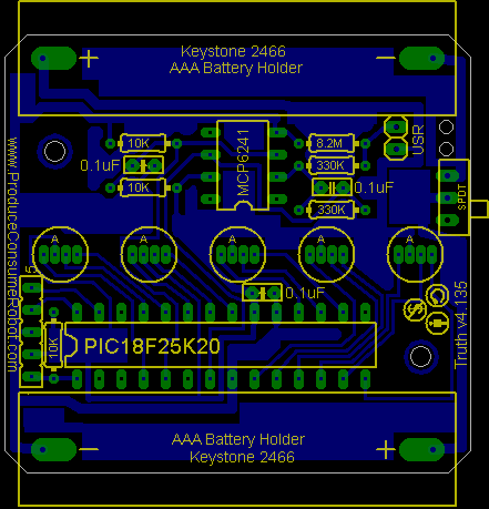
Originally, made with a PIC18F25K20, but I only have a Picaxe28x1 and serial cable.

I think this is a really neat idea, so any other ideas to biofeedback, that someone did with a Picaxe chip would be wonderful.
 

jglenn

Senior Member
You need a C to Basic converter! Never heard of one, so far.

Just make a flowchart and recode it. :eek:
 

LizzieB

Senior Member
You first need to evaluate whether the 28x1 is a suitable replacement for that much faster processor (IIRC it has a 64 MHz clock) in this application.
 

Dippy

Moderator
I agree with JGlenn, go through the code, translate each part into pseudo-code for your flowchart and then recode into PICAXE BASIC. DON't try a line-by-line translation.

Sorry, I know of nothing similar or anything that looks simpler.

Unless you an get Westy interested I reckon the 'translation' will be your job.
I think Andrew is an expert on 'C', maybe he an do it?

Don't worry yourself with the 'includes' at the start, they just call a 'library' so that commands can be referenced.
It uses floating point so a little thought is required (usually quite simple - famous last words) and also numerous samples for averaging, some thought required here too.
The author has used hardware interrupts for timer so you will have to rethink this bit though should be easy on 28X1.

So, in summary, translate the 'principle' of what the code is doing and then rearrange to PICAXE code. Some whole lumps could be change to a couple of PICXE BASIC lines. I haven't looked at it in great detail as I haven't got the time. Others may have the time and I'm sure can point you in the right direction.
But, on the face of it, it doesn't look too difficult. (Maybe in detail its not possible, but I'll leave that to others who haven't got a garden to rotovate).

Good luck.

PS> Do you actually have a schematic?
You posted the artwork.... remember, its only 'simple' to the people that wrote it ;)
 

No0bert

Member
I guess you guys are right, then I will try a new approach. All the board does is measures the difference in resistance and converts them to either red or green lights on the leds. Galvanic Skin Response. Basically when you are stressed you have higher resistance and vice versa. So I need to utilize the Picaxe 28x1's ADC.
 

Dippy

Moderator
Well, thats a start, but without spending hours trying to convert artwork to schematic and then going through the code I cannot say how exactly that device works.
You will, of course, have seen that Op-amp.

I think that, unless someone here has done it or has the spare time, you will have to research some design ideas and then develop (or just copy) a schematic.

But in the meantime, if I were you, I'd have a thorough search on the general subject and the general methods of measurement.

Maybe some kind soul here will do it all for you. Maybe someone here has done it and will share their work. Maybe they're on holiday. Have you searched the Forum?
 

jglenn

Senior Member
How much data can they get from skin resistance? Not like it's EKG or EEG. He should play around with an ohmmeter and finger probes, discs or something. The resistance varies greatly with skin condition and moisture, a huge operational range. Medical units, if they even do this, use conductive cream. It's possible only lie detectors use this variable, and I don't think they really work.

I have seen devices that measure the heartbeat with a led and photoreceptor.

Sounds like they threw a chip with way too much horsepower at a novelty application.
 

gbrusseau

Senior Member
I believe biofeedback monitors pick up the brains tiny beta and alpha brain waves. Common mode signal rejection circuits are used to block out any noise in the signal and amplify the brain waves. One can teach oneself to control the beta and alpha waves of the brain and achieve peace and harmony. Before you all LOL, this is proven technology.
 

jglenn

Senior Member
Reading the first link, it only reads skin resistance, not fancy waveforms.

It is oversimplified, like the Emeter of the Scientologists, bogus as they come. I worked at a co. that made them (Hickok of cleveland).

A wearable device that dynamically reflects the your
/ psycho-emotional response to the world, promoting internal
/ states to be externalized and made into interactive forms
/ of expression. Measuring the galvanic skin response
/ (a marker of emotional arousal commonly used in lie detector
/ tests), this device’s lights turn from blue to red as the
/ wearer becomes aroused. Ask the wearer an evocative question
/ and reveal his or her inner Truth.

:D
 

No0bert

Member
Reading the first link, it only reads skin resistance, not fancy waveforms.

It is oversimplified, like the Emeter of the Scientologists, bogus as they come. I worked at a co. that made them (Hickok of cleveland).

A wearable device that dynamically reflects the your
/ psycho-emotional response to the world, promoting internal
/ states to be externalized and made into interactive forms
/ of expression. Measuring the galvanic skin response
/ (a marker of emotional arousal commonly used in lie detector
/ tests), this device’s lights turn from blue to red as the
/ wearer becomes aroused. Ask the wearer an evocative question
/ and reveal his or her inner Truth.

:D
Thats exactly what I was thinking! The arousal part could correspond to stressful activity. I searched everywhere. I guess I will have to make a comparator circuit.

Off to ze internet!!1!
 
Top