Big LEDs and my Picaxe

212

Senior Member
Hello again, I'm still around here everyday and I been learning a bunch from you guys, THANKS for the help! This time I'm working on an array of 14 IR LEDs. Yes, I'll certainly be using a Picaxe to control the array...on at night... not used during the daytime. It's going to be in another RF video cam for watching critters.

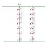
I'm intending on using a 317T as a current regulator, using a 12 volt battery for power. The LEDs will be running around 250ma...rated for 350ma. Now these are not the best in the world, and the quality control is lacking some, so they are not matched real well

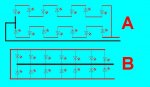
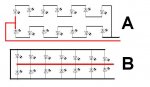
My question is: which way of wiring the things together, and using a current regulator, would keep the current the most even between all the LEDs??? 14 is all that will fit inside the enclosure is why I'm using that number :) I hope I drew this right...it's late and I'm tired. Thanks!

EDIT: Assume I'm color blind OK...duh...I'll get them right when I use real ones :)
 

Attachments

Last edited:

westaust55

Moderator
To specifically answer your question about consistent/equal current:

In your case "A", the current will be the same through all the LED's in the top row and separately (but maybe a slightly different value) through all the LED's in the bottom row.

In your case "B", every LED could draw a different current depending upon the tolerance of the LED's.

Pro's and cons:

In case "A" one faulty or higher impedance LED will reduce the current or stop all LED's in one of the series groups working. Not good to have your IR lamp at half brighness for a single LED failure.


You mention using a current regulator, in simple terms such things work well into one circuit/device but where you have parallel circuits as you have in both cases "A" and "B", there is still the problem of load/current sharing between individula chians of series LED's or between eacdh LED in the case "B" example.
 
Last edited:

212

Senior Member
That was fast! and thank you. Now what I really should have asked...

Which way would/should keep one or more LEDs from being over driven because one or more uses more current than the others? I'm showing my ignorance here, and having a hard time getting the question right. When using resistors to limit the current, and only four per string, one LED may measure 1.4 volts across it and the next 1.55. ONE will burn out. I'm trying to fix that somehow, but don't know the words to use in asking...please try to decipher...

The colors right now lol...
Wired like A
 

Attachments

Last edited:

212

Senior Member
Ok...after we both edited at the same time :) so B would/should have a better chance of staying lit, and not cause burned out LEDs?

Past my bedtime and typing in the dark...

Thanks in advance cause I gotta get outa here.
 

moxhamj

New Member
I think both A and B will burn out the leds.

You need to limit the current through the led. Current is like water flowing down a river, and if you have lots of leds in a row, the current through each one will be the same. So matching won't be such an issue.

Some simple maths. Take 20 leds at 1.5V drop and put them in a row and put 12V on them, and clearly it won't work. So you need to split the leds up into groups.

Say you put 6 leds in each group. 6x1.5V =9V. If you run that off 12V, you have 3V left over. Now you can work out a resistor that will limit the current. V=IR, R=V/I. I= (say) 50mA and V=3, so 3/0.05 = 60 ohms.

You could also use a current regulator instead of the resistor.

Say you then put 8 leds in series instead of 6. 8x1.5=12V, and the supply is 12V V=IR V=zero so the sum doesn't work. In general terms it would be best to have 2-3V drop across the resistor or constant current device (the regulator needs at least 1.2V for instance).

So you can chain up your leds in groups of 6 in series, with a resistor for each. Or a constant current regulator for each chain.

What you can't do though is use one resistor or constant current device for lots of chains of leds. Then the voltage matching will be a problem, and all the current will flow through the group with the lowest total voltage drop.
 

Attachments

Last edited:

Dippy

Moderator
I wouldn't use the 'B' config for sure. It may be OK if all the IR LEDs are exactly equal, but if you are picking IR LEDs out of a draw at random (or worse, getting some second hand ones from Ebay), then it's likely to mess up due to different Vfs.

Talking of Vf (forward Voltage drop) - be aware that the value of Vf can change a lot as you increase the current (If). Just keep this in mind when putting a pile of them in series. Read the DATA SHEET of the LEDs you have, if it is a reputable make it should show a graph of Vf vs If.

I also don't like paralleling things and using a constant current source.
I would be tempted to go for Dracs idea. Or maybe 4 strings of 3LEDS+R using a 9V regulator as a volts regulator though not so efficient obv. To get '100%' even-ness you would have to hand test and pick your LEDs.
 

BeanieBots

Moderator
I can't recommend either A or B. Both are likely to destroy your LEDs. Doc's suggestion is probably your best bet.

Consider B for a minute. You show 14 LEDs paralled. At 250mA each, that would require a drive current of 3.5A. Your 317 won't be able to supply that much current let alone cope with IV power dissipation.
 

boriz

Senior Member
I built a white LED torch many years ago, before you could buy them. It’s housed in an old torch body that I found in a junk shop. It draws about 100mA, roughly 1/4 of the drain of the original filament bulb and with greater light output. The 2 AAAs keep it going for about 10 hours constantly.


The 4 LEDs (5mm) are in series and have about 12-15v across them. The 3v provided by the AAAs is boosted by a little circuit.


The circuit is similar to the second one on this page. I wound the coil myself and used a low Vce(sat) ZTX transistor. No reason why you can’t scale this up and apply it to your IR LED system.
 
Last edited:

212

Senior Member
Thank you again for all the replies, I really appreciate every one of them. Had I asked before drilling the case, I would have used two sets of 6 in a row like the doc said, but I already have 14 holes...duh. Dippy, I once had the data sheet on these, but looked for over an hour tonight and it is just not to be found anymore. I know they are from the big C though, and I'm not real sure it was all that accurate anyway. It's only for me, so I'll wire them in 2 strings of 7 each and try that. I have an array I bought pre-made, and they show right about 1.44 volts across each one...well most of them anyway...so it has a chance of turning out alright...

Hey, they are always making them better, so if this don't work for some reason, I'll try some new ones :)

Boriz, that's impressive! In my case though, I already need 12volts in there to run the camera and transmitter, so I might as well run the light off that too. And don't worry, I'm fixed and will not be breading :)
 

212

Senior Member
Thanks, I might have to get one...or two. Not for this project, but have another in mind.

I found out I can't put 7 LEDs in a string...or shouldn't have anyway...not and try to use the 317. Using a 12 volt battery, all I can push through them is about 107ma. Works fine with 6, but too late. The good news is, they still put out enough light, even at that.

I'm working on the controller now, but I have more thoughts...and of course more questions too. I'll see if I can find the answers myself, but I'll tell ya what I'm thinking. Putting an auto dimmer on the light, so something close up doesn't get washed out...
 
Top