This is my first project and although its working, I am having some intermittent problems.
I am using a network of Picaxes to signal Intercom data, over 2 wires, (bus) and Ov.
My test setup is just 2 stations.
Signalling from Station1 to Station 2 works, every time, however from Staion 1 to Staion 2,
signalling does not work every time, about 1 time in 5 is OK, the other 4 attempts fail.
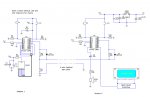
Schematic is here:
http://i.imgur.com/GnPZO.png
Although this is a single wire system, 1 byte sent and receieved in register b0
is sufficient for all my needs, giving 256 codes,or 64 bytes for 4 stations.
All Picaxes on the bus are not using a calling ID, the byte will be decoded per station.
At the moment this is purely test, and on station1 I have used a Common Anode 7 segment display,
if byte 253 is received, then display will change to 8. Eventually, codes will switch relays, and
a second wire will carry purely audio, no data.
This works but intermittantly. Until I can get stable birectional communication, I cannot
proceed further.
I have narrowed down the problem using debug.
Station 2 always sends but when Station 1 fails to receive, no data is received at Station1
(monitored by debug).
I have a feeling this is a timing problem, maybe I have to use calibfreq command.
There are two different programs, samples below:
Station 1 Program below:
Program for Station 2 using OLED
The schematic is purely test at the moment, and sending from 1 to 2 works,
verified with "alpha" and "beta" characters on OLED display.
The opposite way also works, but intermittently.
Bus is held low, via a 10k and 1k resistor (at one end only). Data onto the bus goes via
a 1N4148 diode.
Thanks for any help, insight.
If I dont get this working, I will re-design using a 2 wire system, but would be nice to get this
working.
Thanks in advance.
I am using a network of Picaxes to signal Intercom data, over 2 wires, (bus) and Ov.
My test setup is just 2 stations.
Signalling from Station1 to Station 2 works, every time, however from Staion 1 to Staion 2,
signalling does not work every time, about 1 time in 5 is OK, the other 4 attempts fail.
Schematic is here:
http://i.imgur.com/GnPZO.png
Although this is a single wire system, 1 byte sent and receieved in register b0
is sufficient for all my needs, giving 256 codes,or 64 bytes for 4 stations.
All Picaxes on the bus are not using a calling ID, the byte will be decoded per station.
At the moment this is purely test, and on station1 I have used a Common Anode 7 segment display,
if byte 253 is received, then display will change to 8. Eventually, codes will switch relays, and
a second wire will carry purely audio, no data.
This works but intermittantly. Until I can get stable birectional communication, I cannot
proceed further.
I have narrowed down the problem using debug.
Station 2 always sends but when Station 1 fails to receive, no data is received at Station1
(monitored by debug).
I have a feeling this is a timing problem, maybe I have to use calibfreq command.
There are two different programs, samples below:
Station 1 Program below:
Code:
#picaxe 18M2    ' define pIcaxe
symbol busdata= b1  ' define variable to hold busdata
let busdata = 0
dirsB=%11111111
dirsC=%11111111
pause 500
let pinsB = %11111111 ' blank 7 segment

main:   	'scan input switches
gosub checkbus '  call checkbus here
if  pinC.2 = 1 then let busdata = 224
pause 10
gosub senddata
let pinsB = %11110000   ' if C2 pressed display 3 and set data to 3
pause 100
let pinsB = %11111111	' blank display common anode
endif
if pinC.1 = 1 then  let busdata = 244 ' in B6 pressed display 2 and set data to 2
pause 10
gosub senddata
let pinsB = %01011011	' digit 2
pause 100
let pinsB = %11111111	' blank display common anode
endif
goto main


checkbus:
' Bus is  pin C.7 on 18M2
if pinC.7 = 1 then  'bus is active
do
if pinC.7 = 0 then exit ' wait till bus is clear
loop
serin C.7,N2400_4,b1   ' received byte stored in b1
debug
let pinsB = b1	' display received bus data on 7 segment
pause 250
let pinsB = %11111111	' blank display common anode
endif
if b1 = 253 then
let pinsB = %00000000 ' display 8 if input 1 received

endif
return


senddata:
if pinC.7 = 1 then  'bus is active
do
if pinC.7 = 0 then exit ' wait till bus is clear
loop
endif
'high C.7
'pause 100 ' initialise bus
low C.7
pause 20
serout C.7,N2400_4,(b1)
let dirsC = %00000000 ' set port B pins as inputs
return
Program for Station 2 using OLED
Code:
#picaxe 18M2    ' define pIcaxe
' c7 serial link    b3 sounder  pin 8     b4  oled       pin 9
symbol busdata= b1 ' define b1 to hold busdata
let busdata = 0	' C.7 =Pin16 = Serial Link
dirsB=%11111111  ' B.3=Pin9 = Sounder
pause 5000	     ' B.4 = Pin9 = OLED
serout B.4,N2400,(254,1) ' clear oled after 5 secs
pause 30


main:
gosub checkbus ' new position
if  pinC.2 = 1 then   let busdata = 253  ' if C2 pressed display 3 and set data to 253
	pause 10
	serout B.4,N2400,(254,1) 'clear oled
	serout B.4,N2400,(254,128) 'line 1
	serout B.4,N2400,("Calling Unit 3")
	pause 400 '   wait 0.25 second
	serout B.4,N2400,(254,192) ' Line2
	tune B.3, 2,($16,$18,$19)
	gosub senddata
	pause 2000 ' display 2 seconds
	serout B.4,N2400,(254,1) 'clear oled
endif
if pinC.1 = 1 then  let busdata = 67' in B6 pressed display 2 and set data to 2
	pause 10
	serout B.4,N2400,(254,1) 'clear oled
	serout B.4,N2400,(254,128) 'line 1
	serout B.4,N2400,("Calling Unit 4")
	serout B.4,N2400,(254,192) 'line 2
	tune B.3, 2,($16,$18,$19,$1a)
	gosub senddata
	pause 2000 ' display 2 seconds
	serout B.4,N2400,(254,1) 'clear oled
	pause 30
	endif
'gosub checkbus  ' old position
goto main


checkbus:
if pinC.7 = 1 then  'bus is active
do
if pinC.7 = 0 then exit ' wait till bus is clear
loop
serin C.7,N2400_4,b1   ' received byte stored in b1
pause 10 ' let serin settle
debug
serout B.4,N2400,(254,1) 'clear oled
pause 30
serout B.4,N2400,(254,192) 'line 2
serout B.4,N2400,("Incoming Call ")
serout B.4,N2400,(b1)	' display received bus data on OLED line 2
tune B.3, 2,($19,$18,$16)
pause 2000		' wait 2 second
serout B.4,N2400,(254,1) 'clear oled
pause 30
endif
return


senddata:
if pinC.7 = 1 then  'bus is active
do
if pinC.7 = 0 then exit ' wait till bus is clear
loop
endif
'high C.7
'pause 100 ' initialise bus
low C.7
pause 10 ' delay 10ms for serial in to settle
'serout C.7,N2400,(254,1)
serout C.7,N2400_4,(busdata)
debug
let dirsC = %00000000 ' set port  C pins as inputs
return
The schematic is purely test at the moment, and sending from 1 to 2 works,
verified with "alpha" and "beta" characters on OLED display.
The opposite way also works, but intermittently.
Bus is held low, via a 10k and 1k resistor (at one end only). Data onto the bus goes via
a 1N4148 diode.
Thanks for any help, insight.
If I dont get this working, I will re-design using a 2 wire system, but would be nice to get this
working.
Thanks in advance.