project : battery monitor
picaxe 20x2
my exp, beginner in both electronics and picaxe
hello,
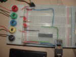
i,ve gone about moniting the voltage of two battery pack the picaxe pack is 3AA bat box, second 4AA both packs are alkaline for now intend to test ni-mh and cad.
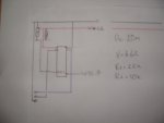
so am reading fom the multi m reads picaxe batt. = 3.80V with a 2.15v on adc pin though a potential divider consisting 1K on V+ and 22K 0v.
reading from the multi m reads second bat, =5.72V.with a 1.02 ADC1 agian potentail divider consisting 22k on 0- and 100k V+
with this programme which i came across and altered (can,t remember the forum member so thank u forum)
Q. is the voltage on the adc pins safe
a plea. could someone elabrate more on the maths used. i feel stupid for asking but i still reading the second manaul and firstand third thankyou,,
i hope others may find this useful start,,
picaxe 20x2
my exp, beginner in both electronics and picaxe
hello,
i,ve gone about moniting the voltage of two battery pack the picaxe pack is 3AA bat box, second 4AA both packs are alkaline for now intend to test ni-mh and cad.
so am reading fom the multi m reads picaxe batt. = 3.80V with a 2.15v on adc pin though a potential divider consisting 1K on V+ and 22K 0v.
reading from the multi m reads second bat, =5.72V.with a 1.02 ADC1 agian potentail divider consisting 22k on 0- and 100k V+
with this programme which i came across and altered (can,t remember the forum member so thank u forum)
Q. is the voltage on the adc pins safe
a plea. could someone elabrate more on the maths used. i feel stupid for asking but i still reading the second manaul and firstand third thankyou,,
i hope others may find this useful start,,
Attachments
-
1.3 KB Views: 32
")