Bargain Picaxe power. Regulated 5v from single AA.

boriz

Senior Member
Hmm. Just saw this: 'Please remove the battery if you don't need to charge your cellphone.'

So I guess it would need a little hacking to add a switch. Still. Can't beat the price :)
 

Dippy

Moderator
"Provides 100-180 mins talking time"
- that's incredible!

Go on boriz, buy a few and let us know if they are good for PICAXE.
 

srnet

Senior Member
On of those will run my 40X2 satellite board.

5.57v @ 3ma
5.38v @ 100ma

Voltage at 100ma does fall off slowly, not sure how low it goes or whether its just a problem with the AA battery.
 

MartinM57

Moderator
...will run, or does run?

5.4v at 100mA with 100% boost efficiency from a 1.5v AA will draw 366mA, or at an over-ambitious estimate of 80% efficiency, 460mA

From a rechargeable AA with a nominal 1.2v, then 416mA and 516mA respectively

My experience of trying to boost even 2.4v to 5v is around 40% efficiency (various designs), so assuming that 40% and 5v out, a rechargeable AA gives a battery current draw of over 1A :)
 

AllyCat

Senior Member
Hi,

Much the same appears to be available from Maplin but with more adapter cables. I bought several (also the "Chameleon" version shown in Maplin's lower thumbnails, which contains a white LED torch and switch as well!) at a price rather lower than their current "offer" price. However, they were bought as much for the multiple adapter cables; being standard 2.5mm mono jacks (IIRC) at the charging end you can make your own adapter cable or replace an unrequired phone end connector with any "unusual" plug (e.g. I have an old phone whch charges via a standard 3.5mm stereo headphone jack).

Personally, I added a small insulating "washer" at the "+" end of the battery so that it can be stored "backwards" inside the case without any drain (a trick the manufacturer seems to have missed). For genuine emergency use I'd recommend an Alkaline Cell, but I normally use NiMH, however either should give a couple of watt-hours so might reasonably charge a small Lithium phone cell (say 400 mAhr).

Sorry, I haven't actually tested the regulation or conversion efficiency, but for PICaxe use I'd suggest one of many possible voltage up-conveters (e.g. the well-known "Joule Thief", or ready-made as found in some single cell "LED torches" or solar garden lights from Pound stores, etc.) and a simple shunt or series regulator, as appropriate.

Cheers, Alan.
 

Haku

Senior Member
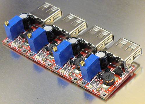
That's a great price for getting 5v from one AA, on a related note yesterday I received these from the land of Chinese eBay:


Adjustable output DC-DC boost converters, output voltage can be set between the input voltage and up to 9V @ 1A, they appear to run ok down to 2v input but I bought them for running 5v stuff from single lithium cells (or 2x/3x AA).
 

chipwich

Member
Every time I see boost converters and Joule-Thief circuits, I keep thinking that a *really* simple design should be possible, if the goal is simply to supply voltage for a PICAXE from a 1.5v cell. The PICAXE itself could serve as the oscillator which drives the txformer. What is the minimum part count with which this could be designed? I'm thinking just a toroid core and a zener diode to protect the PICAXE.

It would not be self-starting, in the sense that initially, you'd need to supply a true Vss (eg, > 1.8v) to power up the PICAXE and start the oscillations. But at that point, you could disconnect the Vss, and let it run from the 1.5v cell. It should be self-sustaining until it runs out of juice.

Has anyone tried this? Can someone provide some guidance for an appropriate (and hopefully very cheap) transformer?


Haku: That's a sharp 4 channel boost converter. But I shudder at the thought of an adjustable voltage of up to 9V coming out via a USB connector. Aren't there quite a few consumer devices that will get damaged, having assumed that the USB supply is a regulated 5v?
 

lauriet

Member
Some time ago, I wrangled one of those emergency charges to hold a button cell, as I needed a tiny tiny power supply for a small self-contained model.
It drove the Picaxe OK.
And a sounder.
And a model motor.
Not for long, obviously, but I have no numbers on that.
 

Haku

Senior Member
@chipwich, it's 4 individual boost converters, I haven't snapped the boards apart yet :)
They arrived tuned to 5.2v-5.35v output but I can see where you're coming from regarding over-volting a USB socket, there are almost identical versions which don't have a variable output but I bought the variable output as they were the cheapest and I can fine-tune the voltage output, as well as remove the USB sockets.
 

boriz

Senior Member
That thing is essentially a joulethief pro. Until I have a play, I dunno if it can also use 2AAs or 3 (with an accompanying increase in efficiency), but it's gotta be worth a punt at that price. I've ordered 4 :)
 

chipwich

Member
The Microchip doc has a "Vdd Self Starting Circuit" which uses a voltage doubler (charge pump) driven by a clock line (or PWM line in the case of the PICAXE) to supply source voltage. This is a great start, though the component count is 7, including a FET. The bare charge pump has 4 components (2 diodes, charge cap, and filter cap), and I think a simple momentary jumper to start voltage doubling should be all that is needed.

Looking a bit further, this looks like a Dickson charge-pump. Seems like this exact topic was discussed here in 2007 at http://www.picaxeforum.co.uk/archive/index.php/t-6976.html . Unfortunately, the whitespace formatting is gone, so I can't read any of the ASCII schematics. But maybe some of the original posters (Hippy, Boriz, etc.) will remember the thread.

Has anyone powered a PICAXE from a single 1.5v cell using a 4 component self-driven charge-pump ( http://en.wikipedia.org/wiki/Voltage_doubler#Dickson_charge_pump )? If so, what values for the components and PWM?
 

manuka

Senior Member
Bah- who needs 100s of mA if running a low demand PICAXE!? Most solar garden lamps use a single NiMH/NiCd AA, & their innards readily hack to suit modest power needs. It's quite some time since I did this, but I recall we managed a PICAXEable ~3mA at 5V when smoothed OK.
 

Attachments

AllyCat

Senior Member
Hi,

At best, each stage of the charge pump can only add the peak-peak "clock" voltage minus a diode forward drop to the input voltage, so you may need many stages to generate a "worthwhile" output voltage.

AFAIK the Joule Thief only really needs a toroidal core because it uses a secondary winding for self-oscillation; a simple solenoidal inductor can be sufficient for an oscillator-driven flyback conveter.

As I've hinted before, if you dismantle a cheap (Pound shop) Garden Solar Light you will very probably find a tiny circuit board carrying what looks like a resistor but is actually an inductor. Replace the NiMH cell with an AA battery in a holder, remove the PV cell (so it thinks it's dark) and the (3 volt white) LED will probably light. However, some versions do seem to need the "kick" of the voltage from the PV cell falling to start them running.

Some (particularly those with a colour-changing LED) already have an "overswing" diode fitted, otherwise add one (e.g. a 1N4148, or slightly better, a Scottky) and an electrolytic capacitor. Keep the LED as a shunt regulator, or replace with a proper regulator.

That will very probably run a PICaxe satisfactorily, but any significant load-demanding peripheral components may need a more sophisticated up converting circuit.

Cheers, Alan.

PS: If you're lucky, the Garden Solar Light PCB may also carry a Schottky diode, but anyway you should have a tiny tag-ended NiMH cell, a slide switch and a PV cell, etc. to put in your "spares" box, all for £1. ;)
 

erco

Senior Member
That's a great price for getting 5v from one AA, on a related note yesterday I received these from the land of Chinese eBay:

Adjustable output DC-DC boost converters, output voltage can be set between the input voltage and up to 9V @ 1A, they appear to run ok down to 2v input but I bought them for running 5v stuff from single lithium cells (or 2x/3x AA).
Haku: Those are interesting. Can you share a link? This is all I found, 5V max output: http://www.ebay.com/itm/261097668334

Edit: found it at http://www.ebay.com/itm/Solar-Boost-Step-Up-USB-Converter-DC-DC-3-3V-9V-Adjustable-Power-Supply-Module-/320963419261?pt=LH_DefaultDomain_0&hash=item4abae91c7d
 
Last edited:
M

mkstevo

Guest
I tried this item in my Beeping Clock to step up from 4.5v (using three AA cells) to 5v to power two PicAxe ICs, one DS1307 and one LCD (not backlit).

http://www.ebay.com/itm/3V-5V-500mA-Mini-DC-DC-Converter

While it worked very well and was small enough to fit inside the battery holder case making the power supply self contained, battery life was barely more than using four AA cells and a series diode and had two (major) disadvantages.

1. It wasn't easy to monitor the battery level (without wiring something from the input of the DC-DC converter to the PicAxe) meaning that the batteries would fail with no warning.
2. The batteries would fail without warning. The power supply would stop so fast that it corrupted the Eeprom of my LCD controller where I had stored my user-definable graphics. Every time I had to replace the batteries, I would have to re-program the PicAxe. It could be that the supply, as it 'collapsed', began to get noisy and the 'noisy' supply corrupted the PicAxe. Either way, with ordinary AA batteries (and currently AA Ni-Mh rechargeables) I can have a low battery warning (which is handy) and I've not had any problems when replacing the batteries.

I should say that I have both a 100nF capacitor directly across each of the PicAxe supply rails, as well as a 47uF and 220uF in the supply stages.
 

inglewoodpete

Senior Member
.... The power supply would stop so fast that it corrupted the Eeprom of my LCD controller where I had stored my user-definable graphics.
Are you saying that you were writing to the EEPROM at the time? Speaking relatively, writing to EEPROM takes a lot of power. If so, possibly why it stopped during a write: the supply was already at the edge when extra demand was created.
 
M

mkstevo

Guest
Are you saying that you were writing to the EEPROM at the time? Speaking relatively, writing to EEPROM takes a lot of power. If so, possibly why it stopped during a write: the supply was already at the edge when extra demand was created.
No that's what I never understood. The UDGs were stored using the 'Data' directive on programming and were only ever 'read' in the program when it started. I suppose as the supply fell it could have repeatedly reset the controller and sent it into a loop where the Eeprom was being continually read and re-read. How this might have overwritten the area though I never fully realised.

I have 'drawn' two UDGs for am and pm where the letters were positioned above one another so they only took up one character position rather than two, and three battery icons showing the state of the battery (Full, half and empty). These would, after replacing the batteries, have various random pixels missing or added to them. Restarting by turning the power off and on wouldn't correct them. Only reprogramming would.

This happened every time the batteries failed while using the DC-DC converter, yet has never happened again (in many weeks) since fitting standard AA batteries without the DC-DC converter. Weird.
 

inglewoodpete

Senior Member
This happened every time the batteries failed while using the DC-DC converter, yet has never happened again (in many weeks) since fitting standard AA batteries without the DC-DC converter. Weird.
I can only suggest two things. The most obvious is: ensure you have a good decoupling capacitor mounted as closely as possible to the power pins of each chip in your project. The other is: does the PICAXE corned have brownout protection enabled? While this consumes a little more power, it shuts the PICAXE down when the supply voltage drops to a preset threshold.
 
M

mkstevo

Guest
Decoupling I had a-plenty. 100nF mounted directly across both of the PicAxe supply pins (two PicAxes, two 100nF capacitors) and a 47uF supply decoupler on one PCB and a further 220uF on the other PCB next to the battery terminals.

I did indeed have the brown-out protection off in the hope of extending the battery life a little. Had the DC-DC converters made a significant difference to the longevity of the batteries, I would have looked further into whether changing this altered the corruption of the UDGs. As the battery life was only extended by one or two hours (in fourteen days) at best, I returned to Ni-Mh AA cells.
 
Top