baler -- an agricultural project

dougyy

New Member
With a long cold winter ahead it seems automating and providing sensors for my old baler would be a nice project. While the total project is lengthy the individual pieces are small and simple enough to wrap my inexperience around.

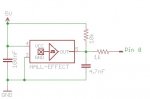
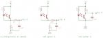
There are several bits of information to sense as a start. First is belt slippage, which can be calculated by comparing a drive roller with an idler roller. Two tachometers and a little math will do the trick. For the tachs I choose a Fairchild phototransistor reflective object sensor (QRB114). Not finding any info on connecting a transistor to a Picaxe input I simply used the switch input circuit, substituting the transistor. With a bit of tweaking on the diode side of the sensor the Picaxe (28X1) receives it. Later when I had time to search the whole web I found a couple of circuits, but so drastically different I need to ask which is the proper way. Attached are the 3 schematics, can anyone point me in the right direction?
 

Attachments

MPep

Senior Member
Version 1 : Input high = Output low
V3: IP high = OP low
V2: IP high = OP high at 2/3 of 5V.

I would use either V1 or V3, with appropriate code of course.

MPep.
 

moxhamj

New Member
I built something similar a few years back. http://drvernacula.topcities.com/12hp_engine_autostart.htm

The D9 plug socket just plugs one to another, so tracing it through the plug/socket, it goes to a 100k/0.1uF low pass filter. I used a 10k to 5V and the opto transistor pulls down, but you can do it either way. I think my circuit is closest to option 2. I was looking for a clean input for a Pulsin. (see the code further down that page).

Definitely test this on the breadboard before building it out in the field!
 

hippy

Ex-Staff (retired)
I'd be surprised if V1 or V2 let enough current through the LED for it operate reliably. I'd choose V3.
 

moxhamj

New Member
Well spotted hippy. The led resistor should be independent of the receiver circuit. Simply a led in series with a resistor (220R) to 5V. So yes, version 3.
 

dougyy

New Member
version 3.
Version 3 it is then, so the 1k resistor before the pin shouldn't be used on a non mechanical switch? I had version 1 breadboarded and working but whether it was reliable wasn't checked.

On my bench the target used for testing was a black disk with a chunk of white electric tape perpendicular to the center, with an rpm of 25-150. In the real world the rpms should fall between 185-545. The target will either be an 8 inch disk or a 4 inch cylinder. The target could simply be half black/half white (very easy to do) or it could have multiple changes. The data sheet says "The area of optimum response approximates a circle .200" in diameter". I could divide up the target into bands about that size (very difficult, but possible) which on the disk would yield a max of about 1200 changes per second. Other than a more accurate count in any given time period is there any reason to favor a higher frequency? Does the Picaxe input have a "sweet spot" for counting?

Should also note the sensors will be about 10 feet from the controller, so if wiring is an issue with higher frequency slower will be better. Also the program isn't in any rush, reading both tachs, calculating the difference and then reading an adc sensor can take as long as 20 seconds.
 

boriz

Senior Member
In a dusty/dirty/working environment, I’d go for magnetic instead of optical every time. Epoxy a magnet onto a rotating part and use a reed or hall device to create pulses. Much more robust than any optical method.
 

dougyy

New Member
In a dusty/dirty/working environment
A magnet and reed switches were my first thought, but there are physical problems. First everything is steel, but the real kicker is the only part that rotates outside the machine is the bearing and its keeper. The shaft is flush with the end of the keeper. A disk bolted onto the end of the shaft will bring me far enough away from the bearing to mount a sensor. That sensor could be a Hall effect, but that would mean having a potential missile 4" off center at 545 rpm. Not a application where one should trust epoxy. I could machine a steel plate with counterbored holes to receive the magnet(s) but it would add a lot of time, and require far more accurate placement and fastening. If the optical is flat out not going to work I'll go ahead with that, but it would be nice to have some odds on it.
 

hippy

Ex-Staff (retired)
so the 1k resistor before the pin shouldn't be used on a non mechanical switch?

It can be included but doesn't necessarily have to be. It serves two purposes, potentially limiting ESD damage and preventing PICAXE failure if the pin you are reading in on for some reason becomes an output high while the transistor is pulling that pin to 0V.

For any short to 0V or short to +V switching ( an active circuit like this, or mechanical switch ) it would be recommended to fit a 1K but you may decide to leave it out. If the pin can be used as an output I'd say fit it, if it can only ever be an input ( eg, pin 3 on 08M ) there's less risk leaving it out.
 

boriz

Senior Member
The magnet does not need to be mounted off centre. Nothing needs to be off centre. No disk required. No vibration. Doesn’t matter what the shaft is made of. Or how fast it turns. If you can access the end face of a shaft, you can use a hall sensor for accurate rotational measurement.

With a small magnet mounted exactly in the centre at the end of a shaft, so that the N/S faces point perpendicular to the shaft axis (like a key handle), a ratiometric hall sensor mounted on the same axis as the shaft, will produce +ve and –ve swings on its output as the shaft rotates.
 

dougyy

New Member
The magnet does not need to be mounted off centre. Nothing needs to be off centre. No disk required. No vibration. Doesn’t matter what the shaft is made of. Or how fast it turns. If you can access the end face of a shaft, you can use a hall sensor for accurate rotational measurement.

With a small magnet mounted exactly in the centre at the end of a shaft, so that the N/S faces point perpendicular to the shaft axis (like a key handle), a ratiometric hall sensor mounted on the same axis as the shaft, will produce +ve and –ve swings on its output as the shaft rotates.
Nice, thats a valuable piece of information I didn't know. Could use that on the idler roller, but the drive roller has other problems. Have enclosed a pic of the shaft end. Note the spring lower left. As the bale forms the springs (there are 2) move across in front of the shaft. Nominally there is an inch of clearance between them, but the back face of the spring is scarred from contact with the shaft. Mounting a disk on the end of the shaft also acts to protect the sensor, and the large diameter is required to get the sensor beyond the bearing mount.

Hippy thanks for the info on the resistor. I've got a kind of generic drawing for the 28X1 and they will be included. The drawing is a template, includes the interface circuit, capacitors, reset, darlington outputs etc (pretty much an X1 project board). Figure its easier to have that and add components than to start from scratch. Are there other components that should normally be present?
 

Attachments

BrendanP

Senior Member
Have a look on Mouser at Cherry's sensor products.

They make HES with provision for bolt/screw mounting and also a magnate mounted into a "cup" with a male thread that can take a nyloc or I guess you drill and tap the end of the shaft and screw the magnets mounting stud into the balers shaft.

Use Locktite on the thread and clean it all with solvent to get rid of all cutting fluid etc. before screwing it in.

Look at these.

http://au.mouser.com/ProductDetail/Cherry-Electrical/AS101001/?qs=/8nQt4pMpTH4cDtNaeWVUQ==

http://au.mouser.com/ProductDetail/Cherry-Electrical/MP201901/?qs=SkbUdWCNujupQQQhg9KHsA==


http://au.mouser.com/catalog/catalogUSD/640/1867.pdf


These would be handy to build the project on. Manukas mate Andrew Hornblow has them made or PM me your address and I'll send you a few over. They work well.

http://www.kei.co.nz/A000273_KiwiPatch Data Sheet.htm


If you need things laser cut (mounting plates/brackets, plastic sheet/ non magnetic etc.) theres a guy in Oregon called BC laser works who is dirt cheap and does a great job. You can send him a rough sketch with dimensions and he will raw it up in CAD for a small fee and cut it out.
 
Last edited:

dougyy

New Member
Magnets in a cup could be mounted not on the shaft but on a disk which in turn would be mounted on the shaft. Locally there are cups with a female thread which would be a better choice. Be a bit difficult to balance, would require a minimum of 3, better to use 6 or 8. Also have some sensors, think they would connect as per the attached schematic. A Hall device is probably more tolerant for clearance, while the datasheet doesn't give dimensions if the magnet passed say 1/4" from the sensor it would probably switch. Still it's lots more work than the optical solution, there is a moving part which is not smooth and the potential missiles are still moving albeit with a mechanical vs a chemical attachment. A safer solution would go back to a thicker disk counterbored to receive the magnets. The info thats missing are some odds on it. The dust/dirt/horrible environment tells me the magnetic solution is better suited, but does it justify the extra time?

I should explain why this all matters anyway. At the start of the hay season when making the first few bales the operator is watching various parts of the machine to see how hard its working as the bale gets bigger. There are obvious signs when things get out of hand, smoking belts, bale stops rotating etc. If the operator knew when the belts started to slip past the expected 5%, went to say 12% that would probably be a maximum bale size. Thats it for the season, bale size is fixed and the main reason for monitoring is over. You leave the monitor running to help catch problems and to help with wrapping because its there, but if the readings are incorrect half the time its only an inconvenience. Because its early in the season environmental conditions are better too. Temperatures moderate, heavy nightime dew to trap dust, machine is cleaner.

So the tachometer functions of this project while important at the start of the season diminish rapidly. There are other sensing functions crucial for the entire season and while I'd thought to use optical for some of them hopefully there are better alternatives you can suggest. After the start of season calibration the bale size becomes a large part of the function. Thats the next step after slippage.
 
Top